
Liquid crystal display devices and methods of manufacturing liquid crystal display devices

Inactive Publication Date: 2012-12-27
SAMSUNG DISPLAY CO LTD
View PDF19 Cites 27 Cited by
  • Summary
  • Abstract
  • Description
  • Claims
  • Application Information

AI Technical Summary

Benefits of technology

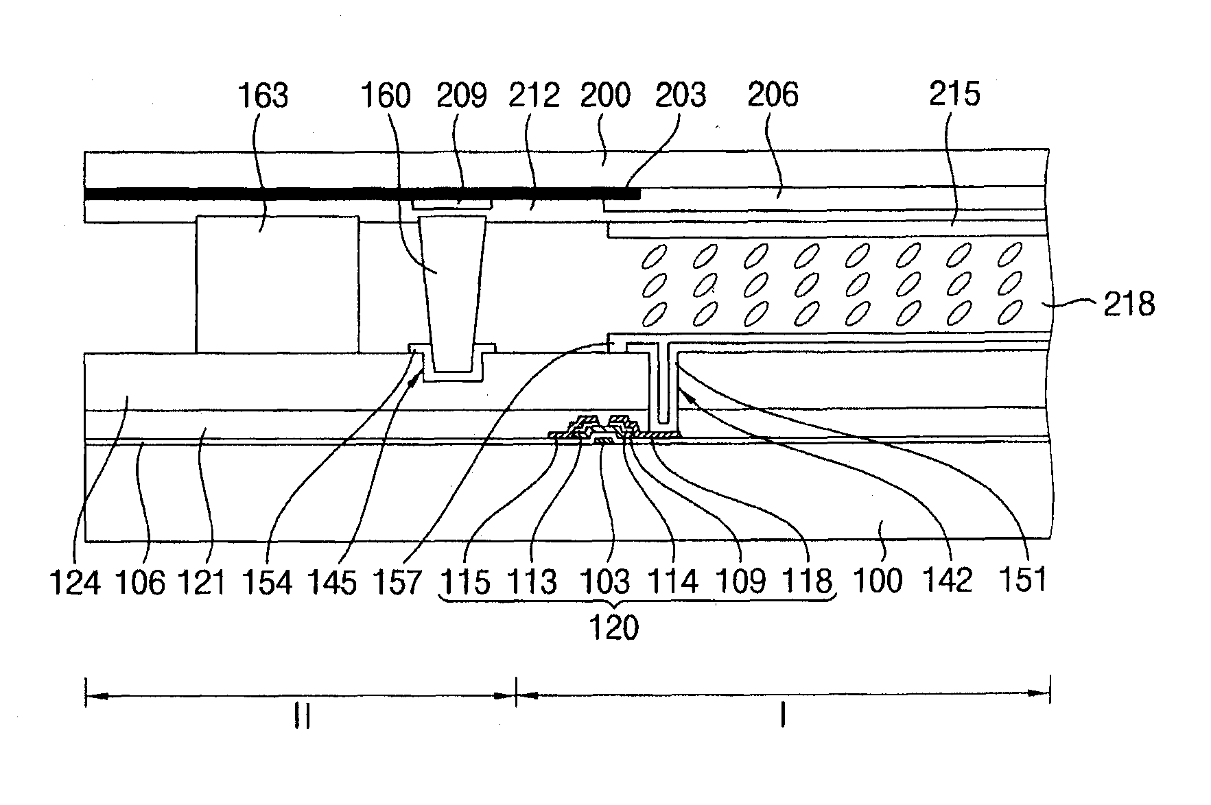
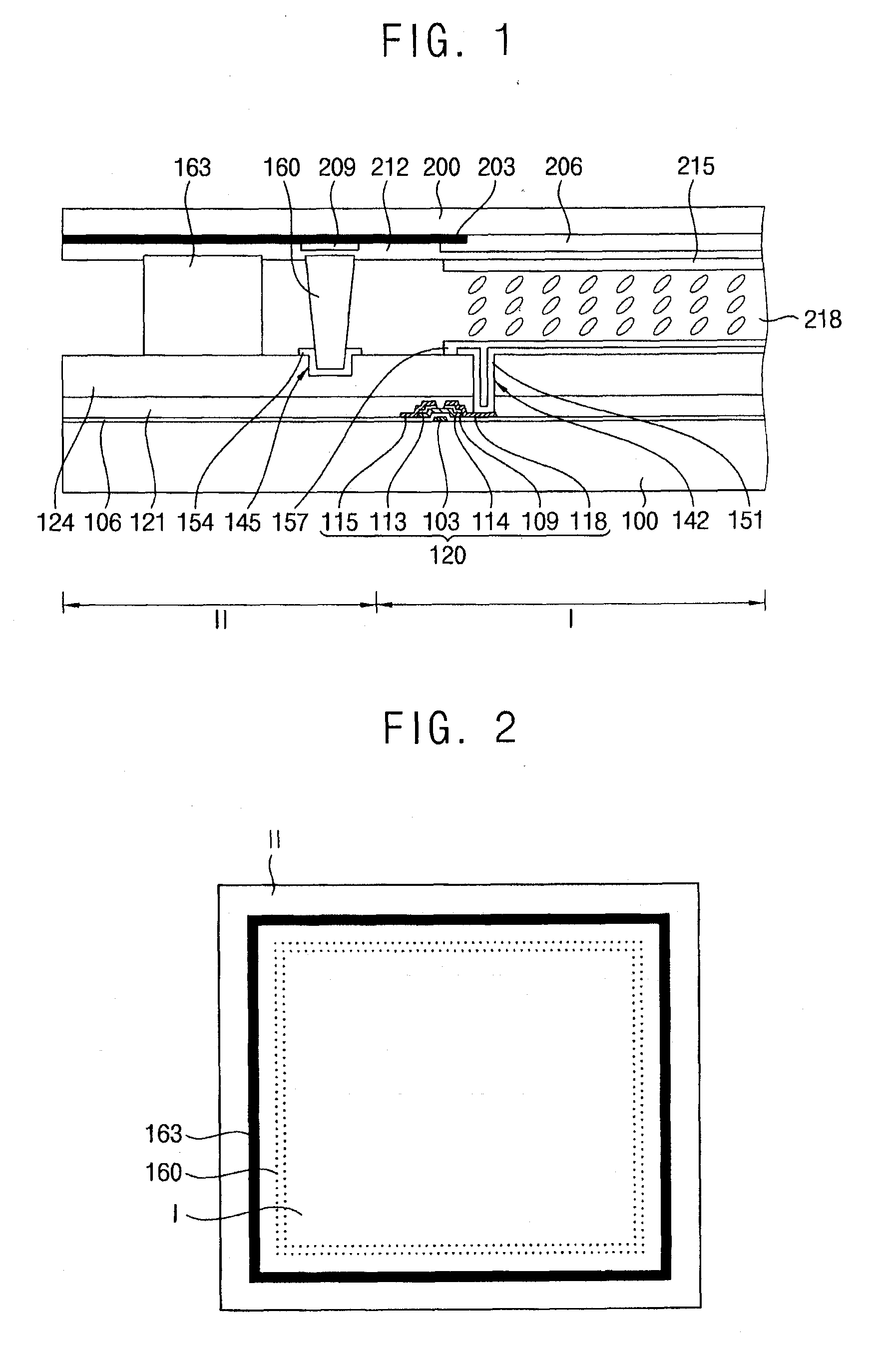
[0009]Example embodiments provide a liquid crystal display device having a blocking structure to prevent defects of a display panel and deterioration of a liquid crystal layer.
[0010]Example embodiments provide a method of manufacturing a liquid crystal display device having a blocking structure to prevent defects of a display panel and deterioration of a liquid crystal layer.
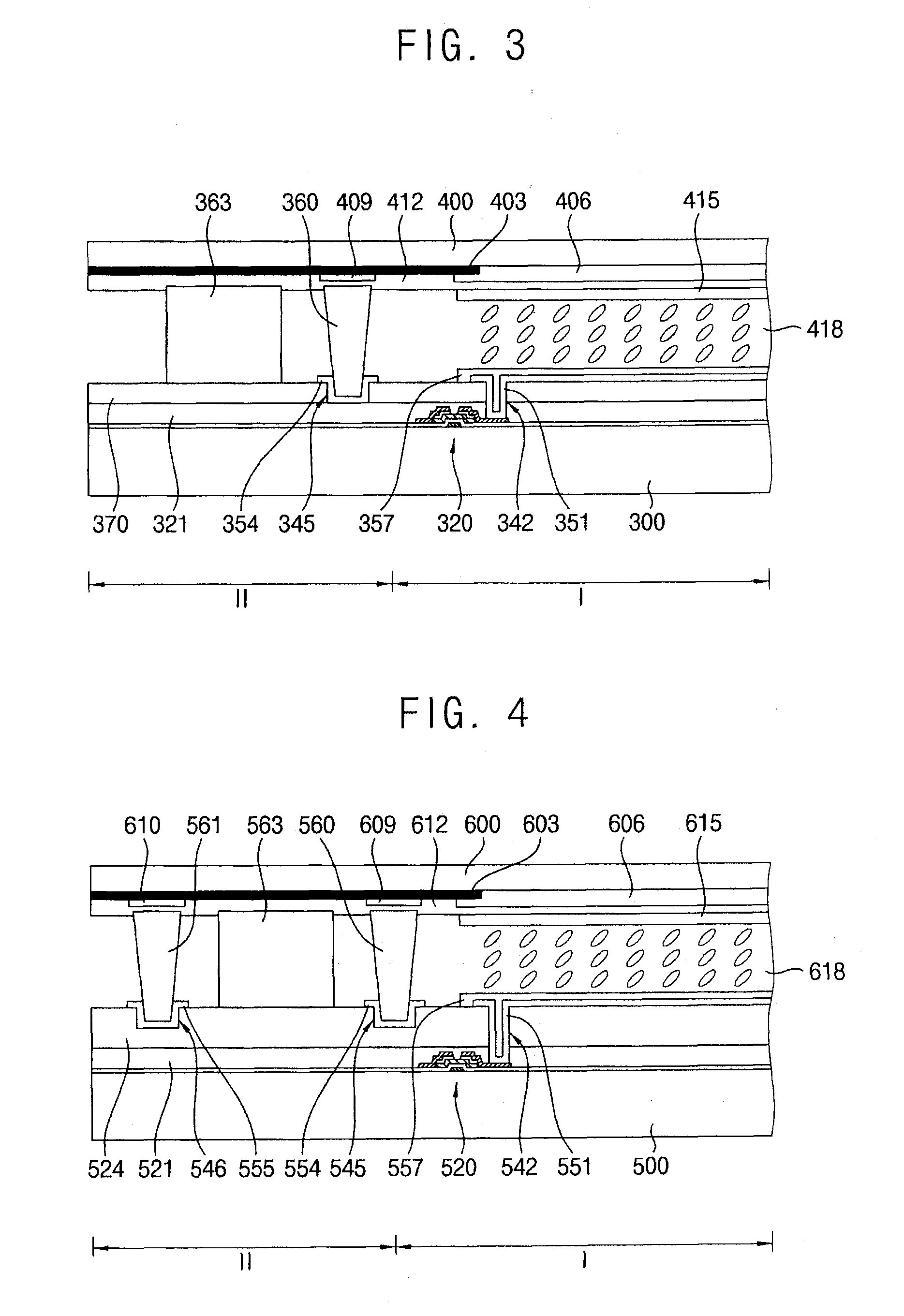
[0037]According to example embodiments, a liquid crystal display device may include at least one blocking structure covering a lower portion of at least one spacer, so that contamination of a liquid crystal layer may be effectively prevented while forming a sealant, and deterioration by penetration of moistures and / or impurities while using the liquid crystal display device may also be effectively prevented. Further, the spacer may be partially received in the blocking structure, so that defects such as stains can be prevented while manufacturing a liquid crystal display device even though height variation of a sealant and / or a spacer may exist.

Problems solved by technology

However, while forming the liquid crystal layer by the above-mentioned method, defects such as stains may be generated along peripheral portions of the liquid crystal display panel in which the sealant is formed, and the liquid crystal layer may be easily contaminated and deteriorated by the sealant.
The defects of the liquid crystal display panel may be generated by various causes such as a radiation time of the UV ray, a processing time of a cleaning process, a processing time of a bonding process, etc. while performing processes for forming the liquid crystal layer, the sealant, the spacer, etc.
In manufacturing of the conventional liquid crystal display device, stains may be severely generated along a seal line of the liquid crystal display panel in accordance with reactions between ingredients in the sealant and the liquid crystal layer.
Additionally, the liquid crystal layer may be easily and frequently deteriorated because moistures or impurities may easily enter into the liquid crystal layer while using the liquid crystal display device.

Method used


Image

  • Liquid crystal display devices and methods of manufacturing liquid crystal display devices
  • Liquid crystal display devices and methods of manufacturing liquid crystal display devices
  • Liquid crystal display devices and methods of manufacturing liquid crystal display devices

Examples


Embodiment Construction

[0046]Various example embodiments will be described more fully hereinafter with reference to the accompanying drawings, in which some example embodiments are shown. The invention may, however, be embodied in many different forms and should not be construed as being limited to example embodiments set forth herein. Rather, these example embodiments are provided so that this description will be thorough and complete, and will fully convey the scope of the invention to those skilled in the art. In the drawings, the sizes and relative sizes of layers and regions may be exaggerated for clarity.

[0047]It will be understood that when an element or layer is referred to as being “on,”“connected to” or “coupled to” another element or layer, it can be directly on, connected or coupled to the other element or layer or intervening elements or layers may be present. When an element is referred to as being “directly on,”“directly connected to” or “directly coupled to” another element or layer, there...


PUM


Abstract

A liquid crystal display device may include a first substrate having a display area and a non-display area, a first electrode located on the first substrate at the display area, a second substrate opposed to the first substrate, a second electrode located on the second substrate at the display area, a liquid crystal layer located between the first electrode and the second electrode, a spacer located between the first substrate and the second substrate in the non-display area, a sealant located adjacent to the spacer, and a blocking structure located beneath the spacer.

Description

CROSS-REFERENCE TO RELATED APPLICATION[0001]This application claims priority under 35 USC §119 to Korean Patent Application No. 2011-0061761 filed on Jun. 24, 2011 in the Korean Intellectual Property Office (KIPO), the contents of which are herein incorporated by reference in their entirety.BACKGROUND[0002]1. Field[0003]Example embodiments relate to liquid crystal display devices and methods of manufacturing liquid crystal display devices.[0004]2. Description of Related Art[0005]A liquid crystal display device displays an image using variations of optical characteristics of liquid crystal molecules included therein. The liquid crystal display device usually includes a liquid crystal display panel and a backlight assembly for providing light to the liquid crystal display panel.[0006]The liquid crystal display panel includes an array substrate on which thin film transistors are arranged, a color filter substrate on which color filters are located, and a sealant for providing a cell ga...

Claims


Application Information

Patent Timeline
IPC IPC(8): G02F1/1339
CPCG02F1/1339G02F2201/501G02F1/133509
Inventor CHOLEE, SEUNG-JAEKIM, JI-SUPARK, GYUNG-SOON
Owner SAMSUNG DISPLAY CO LTD
Learn More