Dispensing method

a technology of dispensing method and liquid volume, which is applied in the field of dispensing method, can solve the problems of difficult to contact a gaseous phase (such as air), difficult to handle this volume of liquid with sufficient accuracy, and difficult to achieve accurate dispensing of liquids. , to achieve the effect of smooth shifting within the tube and accurate dispensing of liquids

Inactive Publication Date: 2012-12-27
SEIKO EPSON CORP
View PDF10 Cites 5 Cited by
  • Summary
  • Abstract
  • Description
  • Claims
  • Application Information

AI Technical Summary

Benefits of technology

[0011]According to the dispensing method of this application example, the first liquid contained in the first vessel and during the respective suction steps and discharge steps is sealed by the second liquid, and therefore is difficult to contact a gaseous phase (such as air). In other words, according to the dispensing method of this application example, the first liquid is handled in the condition of contact with the second liquid during dispensation from the first vessel to the second vessel, and therefore is difficult to contact the air and the like. In this case, evaporation of the constituent components of the first liquid into a gaseous phase, and entrance of other substances such as water through a gaseous phase into the first liquid can be prevented. Accordingly, variations in the concentrations of the solvent and solutes of the first liquid decrease, which contributes to accurate dispensation.
[0017]Moreover, according to the dispensing method of this application example, the first liquid, the third liquid, and the fourth liquid shifted from the first vessel and the third vessel and introduced into the second vessel and during the respective suction steps, mixing step and discharge steps are sealed by the second liquid. Therefore, the first liquid, the third liquid, and the fourth liquid are difficult to contact a gaseous phase (such as air). In other words, during dispensation by the dispensing method of this application example, the first liquid, the third liquid, and the fourth liquid are handled in the condition of contact with the second liquid and therefore difficult to contact the air and the like. In this case, evaporation of the constituent components of the first liquid, the third liquid, or the fourth liquid into a gaseous phase, and entrance of other substances such as water through a gaseous phase into the first liquid, the third liquid, or the fourth liquid can be prevented. Accordingly, variations in the concentrations of the first liquid, the third liquid, and the fourth liquid decrease, which contributes to accurate dispensation.
[0022]According to the dispensing method of this application example, the first liquid shifted from the first vessel and introduced into the second vessel and during the respective suction steps and discharge steps is sealed by the second liquid or the third liquid, and therefore is difficult to contact a gaseous phase (such as air). In other words, according to the dispensing method of this application example, the first liquid is handled in the condition of contact with the second liquid or the third liquid during shift of the first liquid from the first vessel to the second vessel for dispensation, and therefore is difficult to contact the air and the like. In this case, evaporation of the constituent components of the first liquid into a gaseous phase, and entrance of other substances such as water through a gaseous phase into the first liquid can be prevented. Accordingly, variations in the concentrations of the solvent and solutes of the first liquid decrease, which contributes to accurate dispensation.
[0025]According to the dispensing method of this configuration, conductivity given to the third liquid can prevent an unexpected action of either the first liquid or the second liquid when at least either the first liquid or the second liquid is charged, which action may be caused through the electrostatic attractive force or repulsive force produced between the third liquid and the charged first liquid or second liquid in the vicinity of the tip of the tube during the respective discharge steps. Accordingly, the first liquid contained in the first vessel can be more securely dispensed into the second vessel.Application Example 7
[0028]According to the dispensing method of this configuration, water-base liquid does not easily adhere to the inner wall of the tube. Thus, when the first liquid, the third liquid, and the fourth liquid are water solutions, the first liquid, the third liquid, and the fourth liquid can more smoothly shift within the tube during the second suction step and the subsequent respective steps. Moreover, the first liquid, the third liquid, and the fourth liquid are more difficult to remain within the tube in the respective discharge steps. Accordingly, more accurate dispensation of the liquids can be achieved.

Problems solved by technology

It is preferable that the PCR method uses only a small amount (volume) of a reaction liquid in view of cost and efficiency, considering the fact that the specimen and reagent employed for the PCR method are often rare and expensive.
However, the dispensing method used in the techniques of the above references or the like is difficult to handle this volume of liquid with sufficient accuracy.
According to the dispensing method of this application example, the first liquid contained in the first vessel and during the respective suction steps and discharge steps is sealed by the second liquid, and therefore is difficult to contact a gaseous phase (such as air).
In other words, according to the dispensing method of this application example, the first liquid is handled in the condition of contact with the second liquid during dispensation from the first vessel to the second vessel, and therefore is difficult to contact the air and the like.
In this case, the first liquid is difficult to remain within the tube or in the vicinity of the one end of the tube in the second discharge step.
Therefore, the first liquid and the third liquid are difficult to contact a gaseous phase (such as air).
In other words, during dispensation by the dispensing method of this application example, the first liquid and the third liquid are handled in the condition of contact with the second liquid and therefore difficult to contact the air and the like.
Therefore, the first liquid, the third liquid, and the fourth liquid are difficult to contact a gaseous phase (such as air).
In other words, during dispensation by the dispensing method of this application example, the first liquid, the third liquid, and the fourth liquid are handled in the condition of contact with the second liquid and therefore difficult to contact the air and the like.
In this case, the fourth liquid is difficult to remain within the tube or in the vicinity of the one end of the tube during the second discharge step.
According to the dispensing method of this application example, the first liquid shifted from the first vessel and introduced into the second vessel and during the respective suction steps and discharge steps is sealed by the second liquid or the third liquid, and therefore is difficult to contact a gaseous phase (such as air).
In other words, according to the dispensing method of this application example, the first liquid is handled in the condition of contact with the second liquid or the third liquid during shift of the first liquid from the first vessel to the second vessel for dispensation, and therefore is difficult to contact the air and the like.
In this case, the first liquid is difficult to remain within the tube or in the vicinity of the one end of the tube during the second discharge step.
Moreover, the first liquid, the third liquid, and the fourth liquid are more difficult to remain within the tube in the respective discharge steps.

Method used


Image

  • Dispensing method
  • Dispensing method
  • Dispensing method

Examples


first embodiment

1. First Embodiment

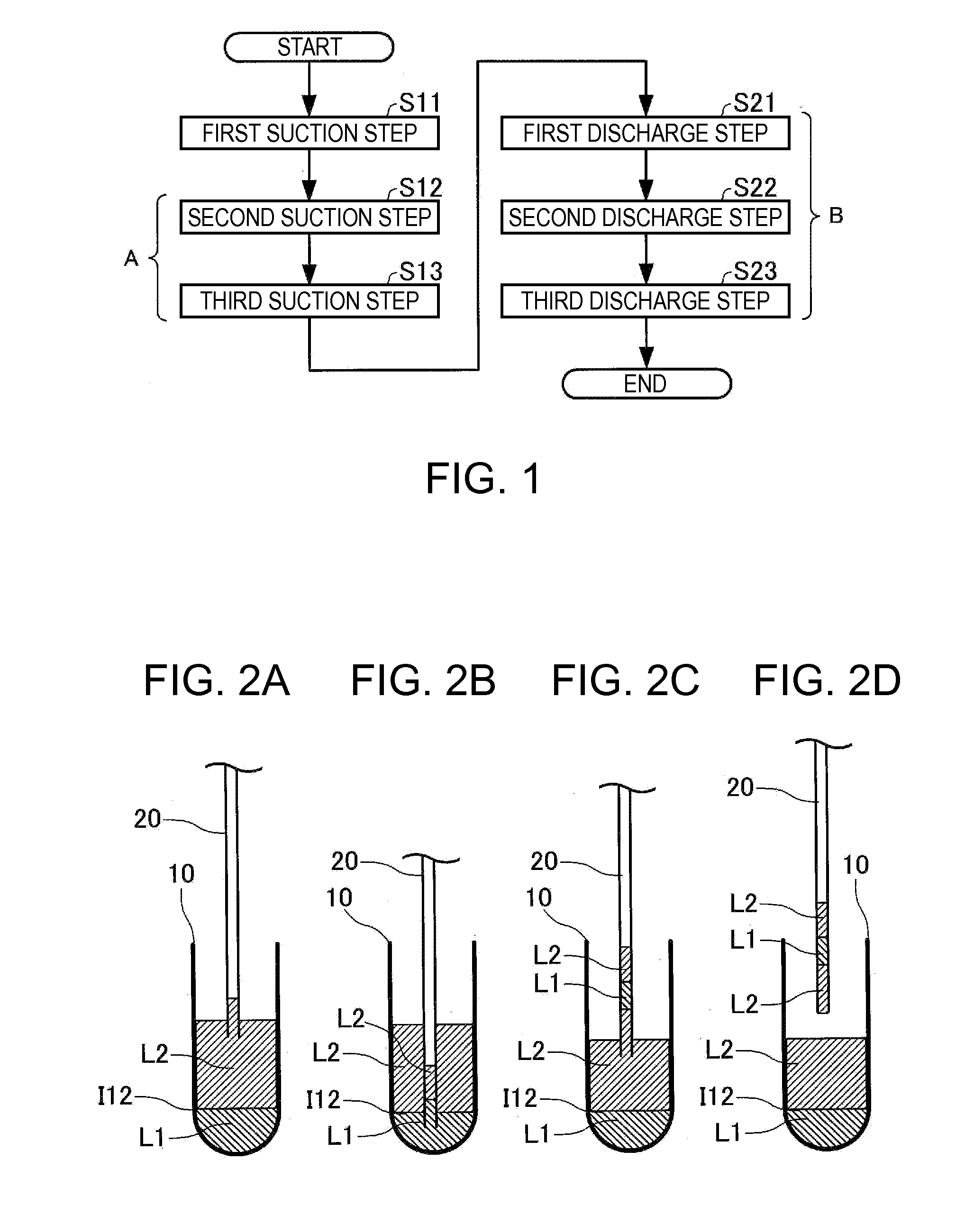
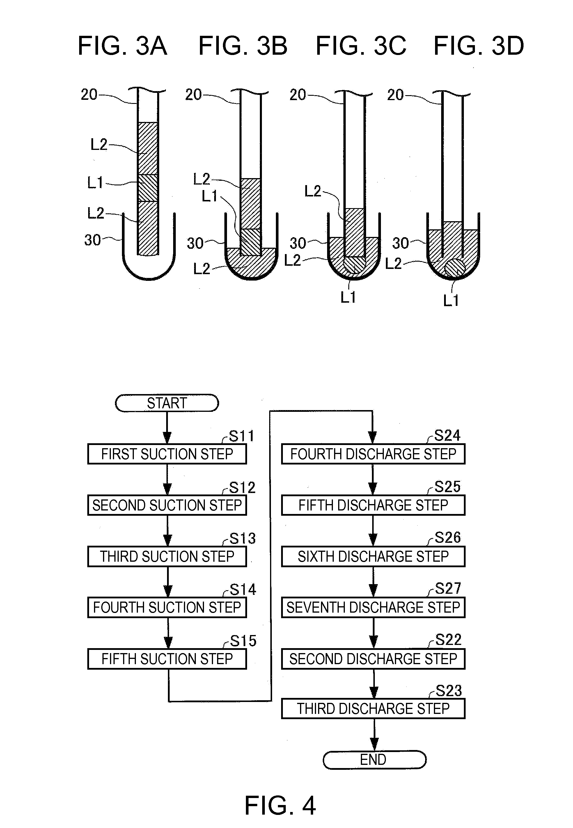
[0056]A dispensing method according to a first embodiment of the invention is hereinafter described. FIG. 1 is a flowchart showing the flow of the dispensing method in this embodiment. Each of FIGS. 2A through 2D and FIGS. 3A through 3D schematically illustrates apart of the steps performed in the dispensing method according to this embodiment. FIG. 2A schematically illustrates a first suction step in this embodiment. FIG. 2B schematically illustrates a second suction step in this embodiment. FIG. 2C schematically illustrates a third suction step in this embodiment. FIG. 2D schematically illustrates a condition after the third suction step in this embodiment. FIG. 3A schematically illustrates a preparatory condition before a first discharge step in this embodiment. FIG. 3B schematically illustrates the first discharge step in this embodiment. FIG. 3C schematically illustrates a second discharge step in this embodiment. FIG. 3D schematically illustrates a third dis...

second embodiment

2. Second Embodiment

[0108]A dispensing method according to a second embodiment of the invention is hereinafter described. FIG. 4 is a flowchart showing the flow of the dispensing method in this embodiment. Each of FIGS. 5A through 5D schematically illustrates a part of the steps performed in the dispensing method in this embodiment. FIG. 5A schematically illustrates a preparatory condition of a fourth suction step in this embodiment. FIG. 5B schematically illustrates the fourth suction step in this embodiment. FIG. 5C schematically illustrates a fifth suction step in this embodiment. FIG. 5D schematically illustrates a condition of the tube after the fifth suction step.

2.1. Structure

[0109]The dispensing method according to this embodiment is a method for dispensing the first liquid L1 contained in the first vessel 10 which stores the first liquid L1 and the second liquid L2, and a third liquid L3 contained in a third vessel 12 which stores the second liquid L2 and the third liquid L...

third embodiment

3. Third Embodiment

[0144]A dispensing method according to the third embodiment of the invention is hereinafter described. FIG. 6 is a flowchart showing the flow of this dispensing method. Each of FIGS. 7A through 7E and FIGS. 8A and 8B schematically illustrates apart of the steps performed in the dispensing method in this embodiment. FIG. 7A schematically illustrates the fifth suction step in this embodiment. FIGS. 7B and 7C schematically illustrate a mixing step in this embodiment. FIGS. 7D and 7E schematically illustrate a condition after the mixing step in this embodiment. FIG. 8A schematically illustrates an eighth discharge step in this embodiment. FIG. 8B schematically illustrates a tenth discharge step in this embodiment.

3.1. Structure

[0145]The dispersing method in this embodiment is a method for dispersing the first liquid L1 contained in the first vessel 10 which stores the first liquid L1 and the second liquid L2, and the third liquid L3 contained in the third vessel 12 wh...


PUM

PropertyMeasurementUnit
volumeaaaaaaaaaa
volumeaaaaaaaaaa
volumeaaaaaaaaaa

Abstract

A dispensing method which dispenses a first liquid contained in a first vessel which stores the first liquid and a second liquid to introduce the first liquid into a second vessel by using a tube.

Description

[0001]This application claims priority to Japanese Patent Application No. 2011-138674, filed Jun. 22, 2011, the entirety of which is hereby incorporated by reference.BACKGROUND[0002]1. Technical Field[0003]The present invention relates to a dispensing method.[0004]2. Related Art[0005]PCR (polymerase chain reaction) is an established technology in the biochemical field. With recent improvement over amplification accuracy and detection sensitivity in the PCR method, even an extremely small amount of a specimen (such as DNA) has been amplified, detected, and analyzed.[0006]It is preferable that the PCR method uses only a small amount (volume) of a reaction liquid in view of cost and efficiency, considering the fact that the specimen and reagent employed for the PCR method are often rare and expensive. Therefore, such a technique which only requires the smallest possible amount of a reaction liquid for the PCR method has been demanded.[0007]JP-A-2004-025148 discloses a method for handli...

Claims


Application Information

Patent Timeline
Patent Type & Authority Applications(United States)
IPC IPC(8): B01L3/00B65B1/04
CPCG01N35/1016B01L3/0241B01L7/52B01L2300/0838B01L2400/0457B01L2400/049Y10T436/25G01N1/14G01N1/38G01N35/1002Y10T436/118339Y10T436/119163Y10T436/2575G01N1/10
Inventor SAITO, YUJITAKAGI, FUMIO
Owner SEIKO EPSON CORP
Why Eureka
Try Eureka