Insulation device

a technology of insulation device and insulation device, which is applied in the direction of hollow articles, trap doors, tubular articles, etc., can solve the problems of common uninsulated loft openings, achieve effective draught exclusion, enhance the fire safety characteristics of insulation device, and prevent fire spread

Inactive Publication Date: 2012-12-27
GRIMES SHAUN
View PDF2 Cites 23 Cited by
  • Summary
  • Abstract
  • Description
  • Claims
  • Application Information

AI Technical Summary

Benefits of technology

[0010]The skirt portion may also be made of an insulating material or may have a pillow-like structure that is filled with an insulating material. This has the advantage of providing the skirt portion with thermal insulation properties in addition to draught exclusion properties.
[0011]Preferably, the skirt portion extends around the entire periphery of the insulating body portion. A skirt portion that extends around the entire periphery of the insulating body portion of the insulation device, rather than just around a part thereof, achieves more effective draught exclusion.
[0012]In a further preferred embodiment of the invention, the insulation device includes a fire retardant additive or a flame retardant additive, each of which enhances the fire safety characteristics of the insulation device by serving to prevent the spread of fire from a loft space into the interior of a building or from the interior of a building to the loft space.
[0013]The insulation device may be provided with a liner having thermal and / or fire retardant properties. Preferably, the liner has at least one perforation. The presence of at least one perforation in the liner reduces the weight of the liner; in some cases the inclusion of at least one perforation can also reduce the manufacturing cost of the liner. The liner may be a metal foil, for example. The liner preferably has a thickness in the range of 10 μm to 5 mm. This range provides a liner of sufficient thickness to achieve an acceptable level of thermal insulation and fire retardant capability whilst avoiding an excessive contribution to the overall weight of the insulation device.
[0014]The insulation material may be selected from any of cellulose, cellulose acetate, fibreglass, paper, cardboard, carpet, wool, polyester, mineral wool, shredded bank notes, foam, cotton, recycled clothing, polystyrene, or any combination thereof. A benefit of using all of these materials, either alone or in combination, is that they have good thermal insulation properties.
[0015]In a further preferred embodiment of the invention, the insulation device is provided with means for attaching the device to a closure for the loft opening. This enables the insulation device to be moved with a closure for the loft opening. It also ensures that the insulation device remains in a fixed position relative to the loft opening, which avoids the insulation device impeding the opening and closing of the closure, and achieves effective insulation of the opening and exclusion of draughts.

Problems solved by technology

Whilst there are many products that can be used to insulate the main area of a loft space, loft openings are commonly left un-insulated allowing heat to escape from the interior of buildings through the loft openings.

Method used


Image

  • Insulation device
  • Insulation device
  • Insulation device

Examples


Embodiment Construction

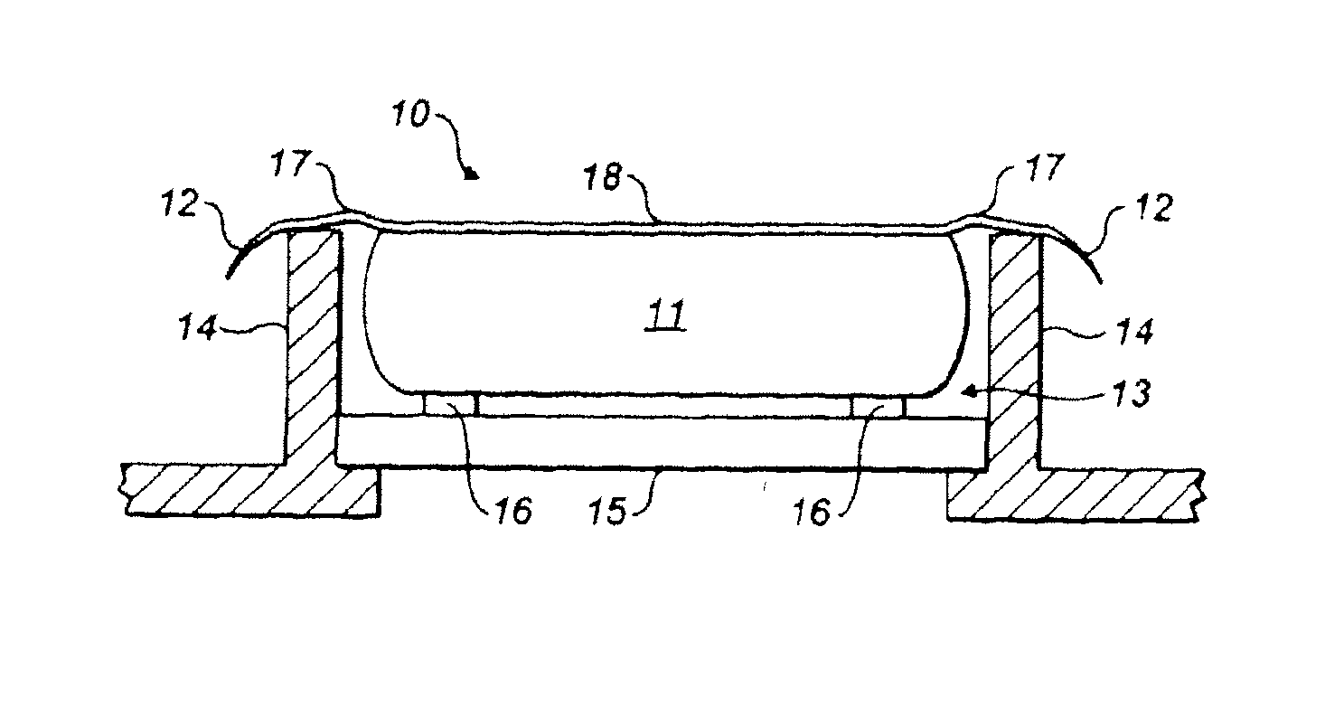
[0025]Referring to FIG. 1, there is shown an insulation device 10 having an insulating body portion 11 and a skirt portion 12 that extends around a periphery of the insulating body portion 11.

[0026]The insulation device 10 is shown arranged in a loft opening 13 that is defined by a frame 14, and is attached to a loft opening closure 15 in the form of an access door by attachment means 16. The attachment means 16 can include glue, sticky-backed plastic, double-sided adhesive tape, hook and loop fasteners, adhesive paste, staples, nails, screws or any other suitable form of attachment. The attachment means 16 can be temporary or permanent and are arranged approximately 1 cm inside the periphery of the insulating body portion 11 but could be placed at any point on the insulating body portion 11 that provides a satisfactory attachment. By virtue of the attachment of the insulating device 10 to the access door 15, the insulating device can move with the access door 15 when it is opened a...


PUM

PropertyMeasurementUnit
thicknessaaaaaaaaaa
thicknessaaaaaaaaaa
lengthaaaaaaaaaa

Abstract

A flexible loft hatch insulation device as suitable to be used on all different types of loft hatches. Manufactured from a variety of different insulation materials including various waste streams. Application includes insulation as well as draught proofing.

Description

CROSS-REFERENCE TO RELATED APPLICATIONS[0001]This application is a continuation of International Application No. PCT / GB2011 / 000323 filed 7 Mar. 2011, which claimed the benefit of Great Britain Application Serial No. 1004042.6, filed 11 Mar. 2010; the contents of all of which applications are incorporated herein by reference in their entireties.FIELD OF THE INVENTION[0002]The present invention relates to an insulation device and in particular, but not exclusively, to an insulation device for a loft opening.BACKGROUND OF THE INVENTION[0003]Many buildings are provided with a pitched roof to allow water to flow off the roof. The pitched roof often creates a relatively large space between a ceiling of the uppermost floor of the building and the roof itself; such a space is commonly referred to as an attic or loft, and is often used as a storage area.[0004]Access to a loft is normally provided via an opening in the ceiling of the uppermost floor of a building and the opening is usually cl...

Claims


Application Information

Patent Timeline
Patent Type & Authority Applications(United States)
IPC IPC(8): B32B1/02B32B3/14B32B3/02
CPCY10T428/1345E06B5/01
Inventor GRIMES, SHAUN
Owner GRIMES SHAUN
Why Eureka
Try Eureka