Configurations and methods for acid gas and contaminant removal with near zero emission

a technology of contaminant removal and gas processing, applied in the direction of liquid degasification, separation processes, sulfur compounds, etc., can solve the problems of increasing solvent circulation and energy consumption, increasing solvent absorption, and increasing the temperature rise of the absorber. , to achieve the effect of increasing the selective absorption of hydrogen sulfide and reducing the temperature rise of the absorber

Inactive Publication Date: 2006-07-13
FLUOR TECH CORP
View PDF3 Cites 51 Cited by
  • Summary
  • Abstract
  • Description
  • Claims
  • Application Information

AI Technical Summary

Benefits of technology

[0013] In one aspect of the inventive subject matter, a gas treatment plant has an absorber that receives (a) a feed gas comprising carbon dioxide and hydrogen sulfide, (b) a carbon dioxide saturated lean solvent, and (c) that produces an overhead vapor comprising at least a portion of the carbon dioxide, wherein a lean

Problems solved by technology

However, with increasing acid gas and other contaminant content, current treating processes often require relatively large quantities of energy and may further require additional processing equipment.
Particularly, when the feed gas 1 comprises relatively large CO2 quantities (e.g., greater than 50%), co-absorption of CO2 in such plants requires higher solvent circulation and higher energy consumption and also produces an acid gas rich in CO2 (typically 80%) that is an undesirable acid gas for the sulfur plants.
As a result, and especially where the feed gas comprises relatively high concentrations of acid gas and other contaminants, the capital and operating costs required by these processes are generally very high.
Very often, post treatment of the treated gas from these units with additional processing equipment is required, due to the fact that elimination of contaminants is frequently below desirable levels.
Unfortunately, most of such methods tend to be relatively inefficient and costly, and where contaminants are removed by a fixed bed absorbent process, they may further pose a disposal problem for the spent absorbent.
Therefore, various problems associated with operating efficiency, effluents; emissions, and product qualities, particularly in the downstream sulfur recovery unit and tail gas unit, still re

Method used


Image

  • Configurations and methods for acid gas and contaminant removal with near zero emission
  • Configurations and methods for acid gas and contaminant removal with near zero emission
  • Configurations and methods for acid gas and contaminant removal with near zero emission

Examples


Embodiment Construction

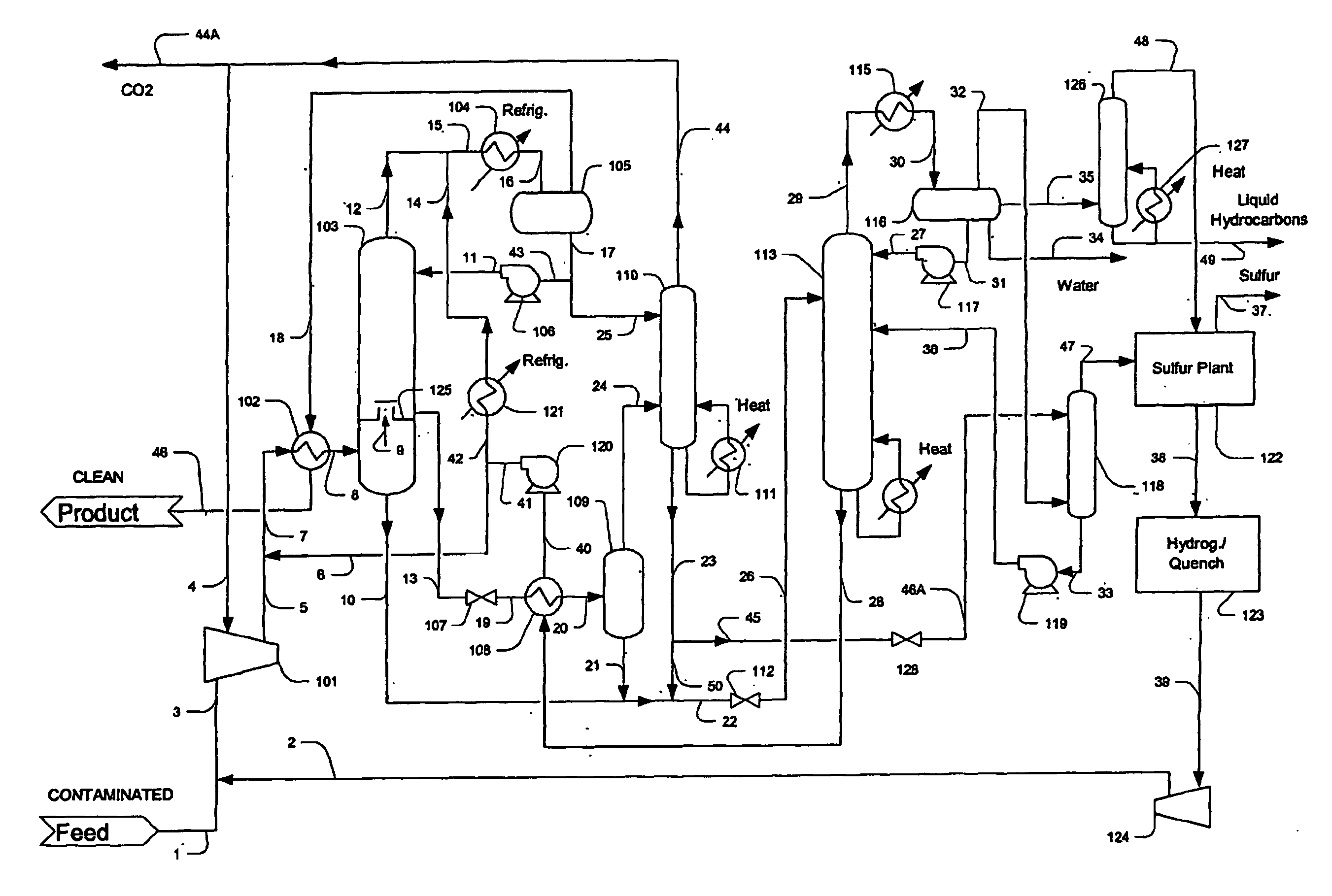
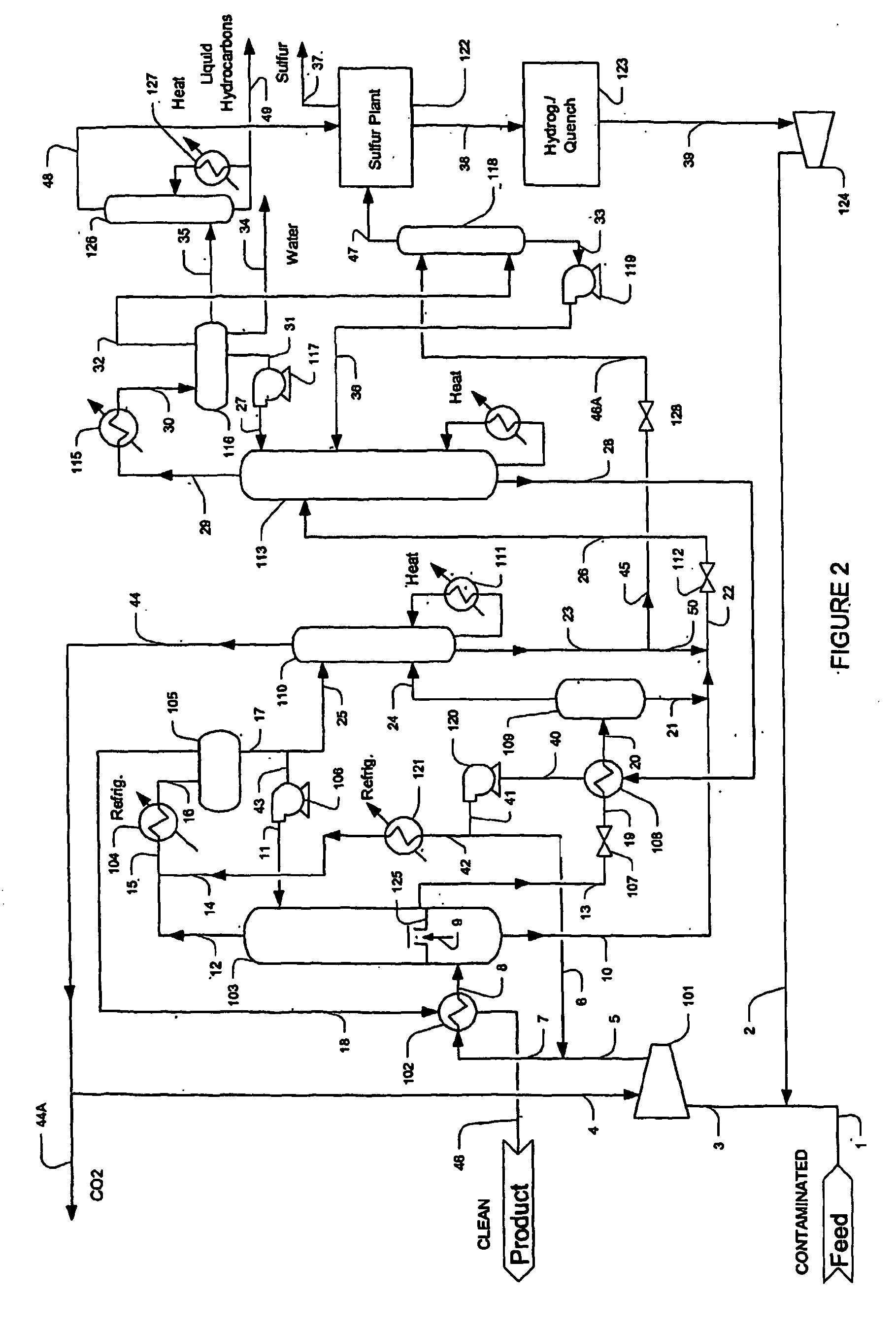
[0020] The inventors discovered that gas comprising relatively high levels of acid gases and other contaminants can be treated in a process that significantly reduces, if not even almost eliminates emissions of sulfurous components, hydrocarbons, and / or other contaminants. Contemplated process will typically produce a dehydrated gas with a low hydrocarbon dewpoint that will meet pipeline sales gas specifications.

[0021] Furthermore, contemplated configurations will produce a hydrogen sulfide rich and hydrocarbon depleted gas that can be efficiently processed in a sulfur plant, and the tail gas of the sulfur plant is (after hydrogenation and quenching) recycled back to the feed gas. Still further, the hydrocarbons separated and recovered from the feed gas in contemplated configurations are generally suitable for use as a liquid fuel after further processing. Thus, it should be especially appreciated that contemplated configurations and methods allow for feed gas processing of a conta...


PUM

PropertyMeasurementUnit
Temperatureaaaaaaaaaa
Pressureaaaaaaaaaa
Residual entropyaaaaaaaaaa

Abstract

A gas (1) comprising hydrogen sulfide, carbon dioxide, and hydrocarbon contaminants is treated in a plant (FIG. 2) in a configuration in which waste streams are recycled to extinction. In especially preferred aspects of contemplated methods and configurations, hydrogen sulfide and other sulfurous components are converted to a sulfur product (37), carbon dioxide (44A) is separated at a purity sufficient for enhanced oil recovery or sale, and hydrocarbon contaminants are purified to a marketable hydrocarbon product (49).

Description

[0001] This application claims the benefit of U.S. provisional patent application with the Ser. No. 60 / 434,358, which was filed Dec. 17, 2002 and which is incorporated by reference herein.FIELD OF THE INVENTION [0002] The field of the invention is gas processing and treating, and especially gas processing and treating with near zero emissions. BACKGROUND OF THE INVENTION [0003] Natural gas streams that contain low levels of acid gases and other contaminants can be economically treated by a wide variety of known treating processes. However, with increasing acid gas and other contaminant content, current treating processes often require relatively large quantities of energy and may further require additional processing equipment. [0004] An exemplary known gas treatment configuration that employs the use of a physical solvent is depicted in prior art FIG. 1 in which an absorber 203, a flash drum 205, a recycle compressor 206, exchanger 207, a solvent regenerator 208, a reboiler 209, a ...

Claims


Application Information

Patent Timeline
IPC IPC(8): B01D53/14
CPCB01D53/1406B01D53/1456B01D53/1462B01D53/1487B01D53/8612C01B17/0404C01B17/0408Y02C10/06Y02E50/346Y02C20/40Y02P20/151
Inventor MAK, JOHNGRAHAM, CURT
Owner FLUOR TECH CORP
Why Eureka
Try Eureka