Ultrasonic diagnostic apparatus and ultrasonic image display method

a diagnostic apparatus and ultrasonic technology, applied in diagnostics, medical science, applications, etc., can solve the problems of not being able to perform the juxtaposing and display of elastic images and tomographic images of cross-section arbitrarily cut out from volume data

Inactive Publication Date: 2012-12-27
HITACHI LTD
View PDF3 Cites 8 Cited by
  • Summary
  • Abstract
  • Description
  • Claims
  • Application Information

AI Technical Summary

Benefits of technology

[0017]In accordance with the present invention, it is possible to juxtapose and display an elastic image and a tomographic image with respect to a cross-section which is arbitrarily cut out from volume data.

Problems solved by technology

The above-mentioned Patent Documents do not disclose the technique, with respect to the cross-section which is arbitrarily cut out from volume data, to juxtapose and display a tomographic image and an elastic image.
Thus juxtaposing and displaying of an elastic image and a tomographic image of the cross-section which is arbitrarily cut out from volume data has not been possible to perform.

Method used


Image

  • Ultrasonic diagnostic apparatus and ultrasonic image display method
  • Ultrasonic diagnostic apparatus and ultrasonic image display method
  • Ultrasonic diagnostic apparatus and ultrasonic image display method

Examples


embodiment 1

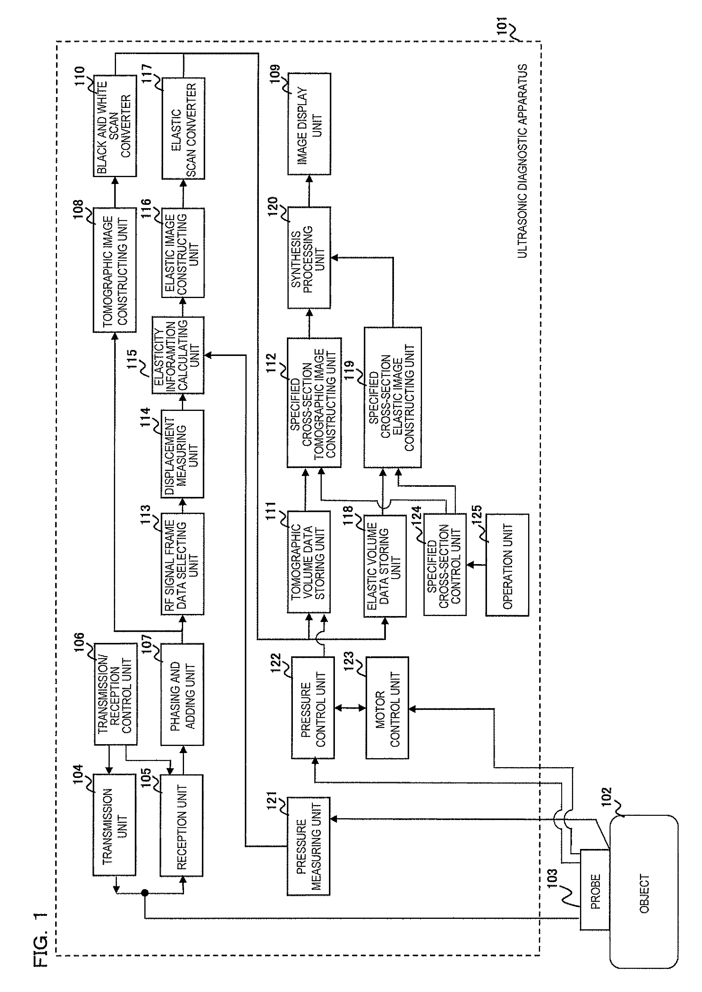
[0026]FIG. 1 shows the configuration of an ultrasonic diagnostic apparatus 101 related to the present invention. As shown in FIG. 1, the ultrasonic diagnostic apparatus comprises an ultrasonic probe 103 to be used by applying to an object 102, a transmission unit 104 configured to repeatedly transmit ultrasonic waves to the object 102 via the ultrasonic probe 103 at intervals, a reception unit 105 configured to receive the time-series reflected echo signals generated from the object 102, a transmission / reception control unit 106 configured to control the transmission unit 104 and the reception unit 105, and a phasing and adding unit 107 configured to perform phasing and adding of the reflected echo signals received by the reception unit 105.

[0027]The ultrasonic probe 103 is provided with a plurality of transducers arrayed therein, to transmit / receive ultrasonic waves to / from the object 102 via the transducers. The ultrasonic probe 103 is formed by a plurality of rectangle or fan-sha...

embodiment 2

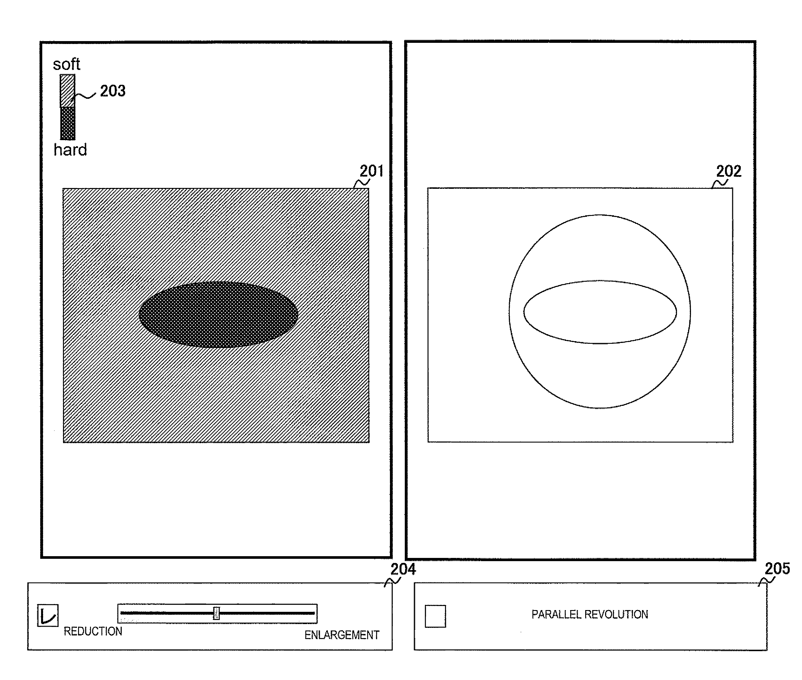
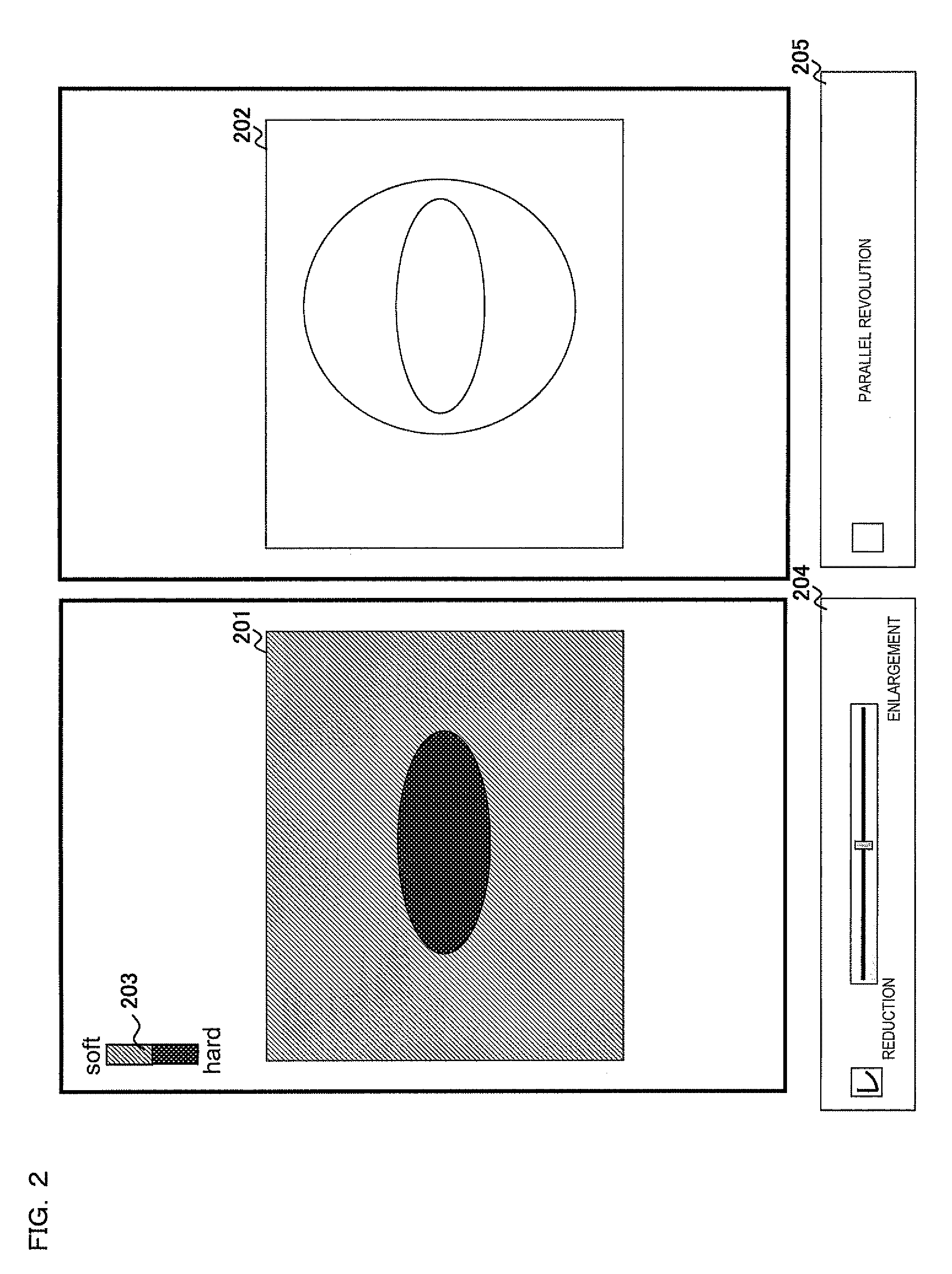
[0067]The second embodiment will be described referring to FIGS. 1-4. The difference from the first embodiment is that the image display unit 109, when an elastic image (or a synthetic image) displayed on the image display unit 109 is specified by the operation unit 125, displays the tomographic image of the same cross-section as that of the specified elastic image in parallel with the elastic image.

[0068]As shown in the MPR display pattern in FIG. 3, the image display unit 109 displays a rendering image 301 created on the basis of the tomographic volume data and the elastic volume data, and elastic images 302˜304 in orthogonal three cross-sections of the tomographic volume data and the elastic volume data. The elastic images 302˜304 are displayed with a scale bar 305 that shows hardness.

[0069]When the synthesis processing unit 120 executes rendering by associating the 3-dimensional position and the direction in the tomographic volume data stored in the tomographic volume data stori...

embodiment 3

[0080]The third embodiment will be described referring to FIGS. 1 and 5. The difference of the present embodiment from the first and second embodiments is that the image display unit 109 can display the positional information of the cross-section which is specified by the operation unit 125.

[0081]In the same method as in the first and second embodiments, an elastic image 501 (or a synthetic image), a tomographic image 502 of the same cross-section as that of the elastic image 501, and a scale bar 507 are displayed on the display unit 109.

[0082]Further, the positional information of the specified cross-section is also displayed on the image display unit 109. The image display unit 109 displays an orientation image 503 to be displayed so that the 3-dimensional position and the direction of the cross-section of the elastic image 501 can be visually identified and an orientation image 505 to be displayed so that the 3-dimensional position and the direction of the cross-section of the to...


PUM


Abstract

An ultrasonic diagnostic apparatus comprises an operation unit that arbitrarily specifies a cross-section; a specified cross-section tomographic image constructing unit that cuts and constructs a tomographic image of the specified cross-section from tomographic volume data that is stored in the volume data storing unit; a specified cross-section elastic image constructing unit that cuts and constructs an elastic image of the specified cross-section from elastic volume data that is stored in the volume data storing unit; and a display unit that displays in parallel the tomographic image and the elastic image that are constructed by the specified cross-section tomographic image constructing unit and the specified cross-section elastic image constructing unit.

Description

FIELD OF THE INVENTION[0001]The present invention relates to an ultrasonic diagnostic apparatus and an ultrasonic image display method for displaying a tomographic image or an elastic image showing the hardness or softness of biological tissue of an object using ultrasonic waves.DESCRIPTION OF RELATED ART[0002]An ultrasonic diagnostic apparatus has been used for transmitting ultrasonic waves to the inside of an object to be examined via an ultrasonic probe, generating volume data by receiving the reflected echo signals in accordance with the configuration of the biological tissue from the inside of the object, and displaying a 3-dimensional tomographic image and a 3-dimensional elastic image (for example, Patent Document 1). Further, a method is proposed to cut out an arbitrary cross-section from the obtained volume data and display a tomographic image (for example, Patent Document 2).PRIOR ART DOCUMENTSPatent Documents[0003]Patent Document 1: JP-A-2008-259605[0004]Patent Document 2...

Claims


Application Information

Patent Timeline
Patent Type & Authority Applications(United States)
IPC IPC(8): A61B8/14
CPCA61B8/08A61B8/14A61B8/463A61B8/5246A61B8/485A61B8/523A61B8/469
Inventor SAWAYAMA, YUKIWAKI, KOJIIIMURA, TAKASHI
Owner HITACHI LTD
Why Eureka
Try Eureka