
Methods and systems for adjusting an external fixation frame

a fixation frame and external technology, applied in the field of methods, tools and systems for adjusting the external fixation frame, can solve the problems of limited componentry, very rapid application, long and daunting process,

Inactive Publication Date: 2012-12-27
STRYKER EURO OPERATIONS HLDG LLC
View PDF13 Cites 71 Cited by
  • Summary
  • Abstract
  • Description
  • Claims
  • Application Information

AI Technical Summary

Benefits of technology

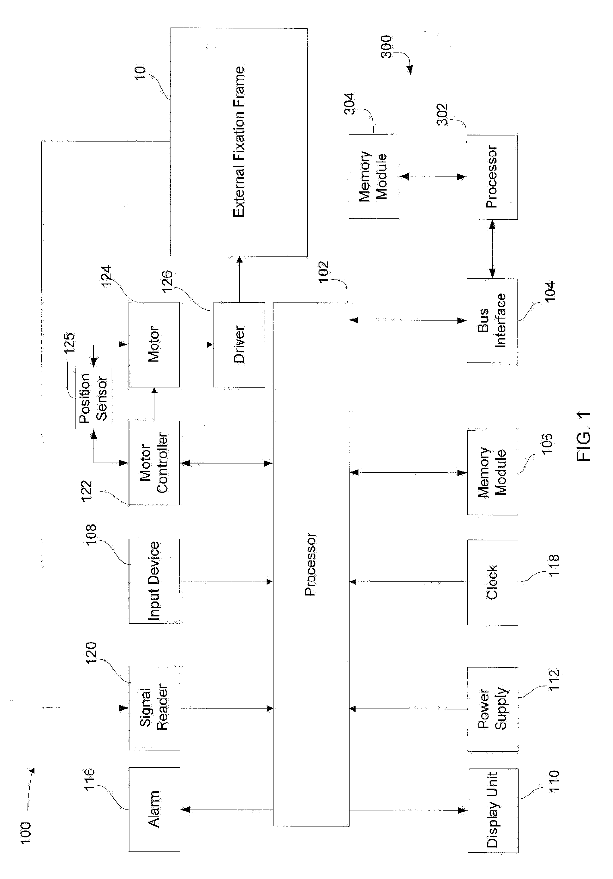
[0019]As discussed above, the present disclosure also relates to tools for implementing a correction plan in an external fixation frame having a plurality of screws. In one embodiment, the tool includes a driver adapted to engage and rotate each of a plurality of screws of an external fixation frame; a motor coupled the driver and adapted to rotate the driver; a controller connected to the motor and configured to control operation of the motor; and a processor. The

Problems solved by technology

These frames are characterized by limited componentry and very rapid application.
However, mastery of the techniques and the products themselves can be a long and daunting process that it is not attractive to many users.
The Ilizarov system can provide an external fixation device that could provide gradual correction along and about six axes; however, such a device would require many parts and would be relatively complicated to build and use in a clinical situation.
Patients, however, may not desire to visit the physician's office every time an adjustment is needed.
In some occasions, patients may not adjust their own external fixator according to the correction plan for a variety of reasons.
For instance, patients may not understand how to use the external fixator correctly.
In addition, when the patients themselves adjust the external fixators, physicians may not even know whether patients are in fact adjusting the external fixators according to the correction plan.

Method used


Image

  • Methods and systems for adjusting an external fixation frame
  • Methods and systems for adjusting an external fixation frame
  • Methods and systems for adjusting an external fixation frame

Examples


Embodiment Construction

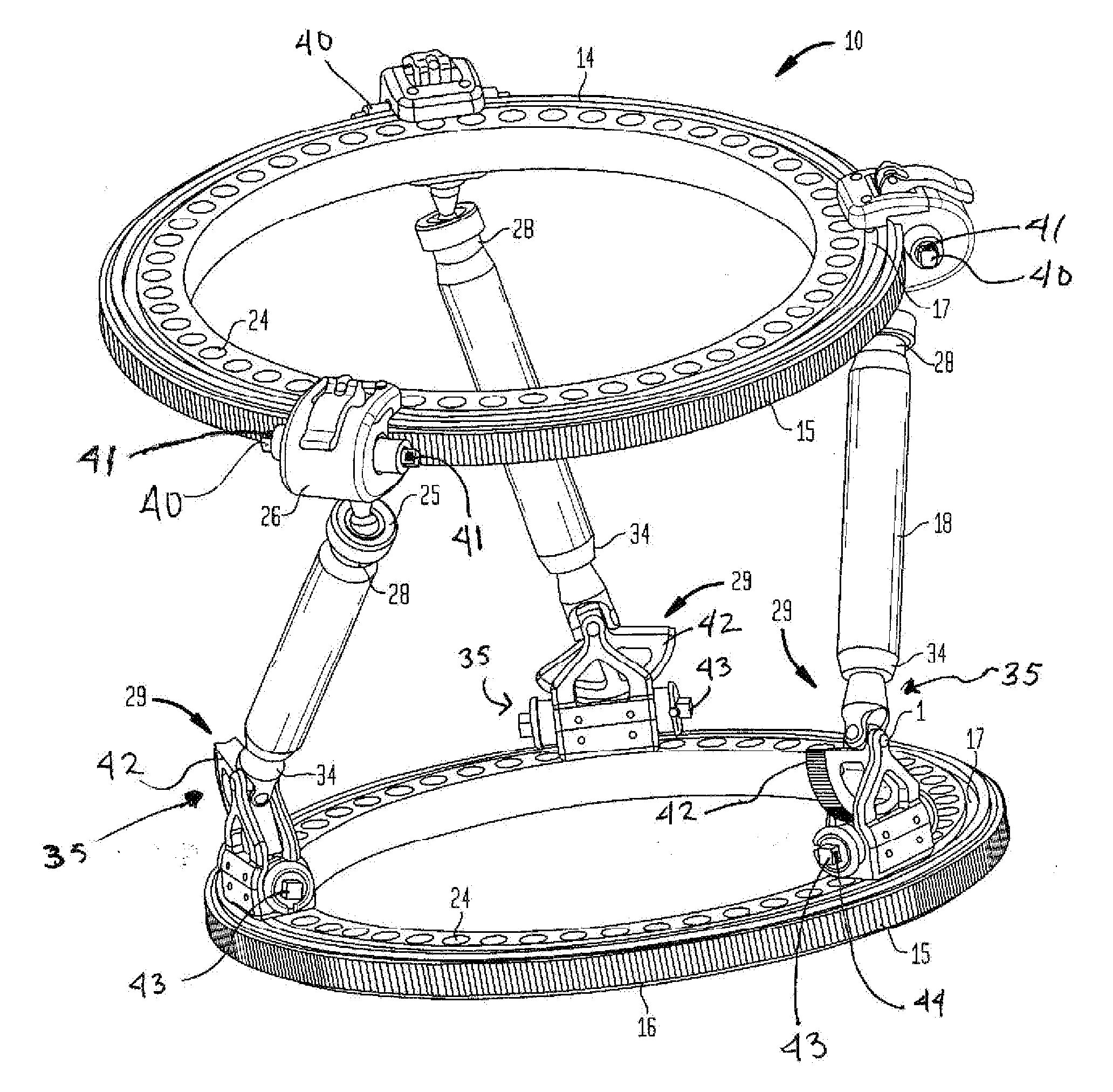
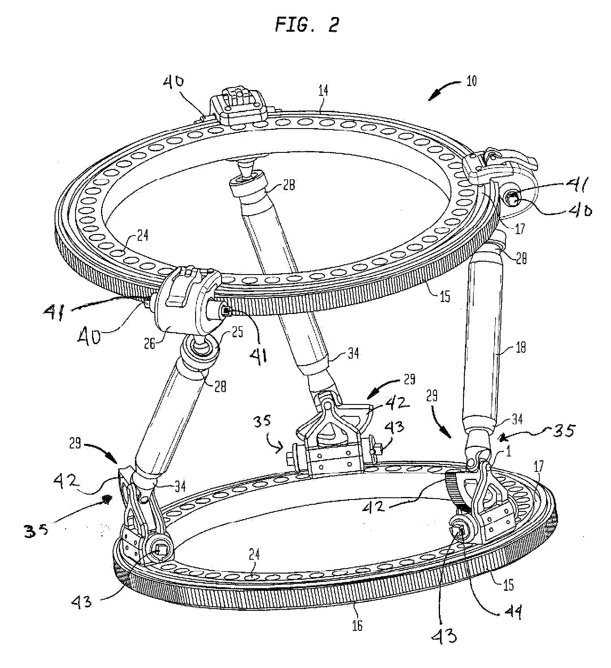
[0033]The present disclosure will now describe in detail embodiments of methods and systems for adjusting an external fixation frame with reference to the drawings in which like reference numerals designate identical or substantially similar parts in each view. As used herein, “clinician” refers to a physician, surgeon, nurse or other care provider and may include support personnel.

[0034]FIG. 1 schematically depicts a tool or system 100 for adjusting any suitable external fixation frame 10. In general, the system or tool 100 includes processor 102, such as a microprocessor or central processing unit, capable of executing instructions for adjusting an external fixation frame 10. The processor 102 may include any suitable bus interface 104 for establishing communication between tool 100 and an external host computer 300, such as a personal computer. Suitable bus interfaces 104, include, but are not limited to Universal Serial Bus (UBS), a serial port, a parallel port, IEEE 1394 interf...


PUM


Abstract

A tool for implementing a correction plan in an external fixation frame having a plurality of adjustment elements or screws, for example, generally includes a driver, a motor, a controller, and a processor. The driver is adapted to engage and rotate each of the screws. The motor is coupled the driver and adapted to rotate the driver. The controller is connected to the motor and configured to control operation of the motor. The a processor adapted configured to: receive correction plan data; receive identification data including information for identifying at least one of the plurality of screws; determine movement of at least one of the plurality of the screws based on the correction plan data and the identification data; and send signals indicative of the determined movement to the controller in order to rotate at least one of the plurality of screws according to a predetermined correction plan.

Description

BACKGROUND OF THE INVENTION[0001]The present disclosure relates to methods, tools and systems for adjusting an external fixation frame. More particularly, the present disclosure relates to methods tools and system for repositioning the components of an external fixation frame according to a correction plan.[0002]The external fixation market can be divided into two major segments: acute trauma and reconstructive. The customers, products, and needs of each segment are distinctly different. The trauma segment is dominated by modular fixators. These frames are characterized by limited componentry and very rapid application. Consequently, they are known for being fairly simple products. Most of these frames are used for temporizing fixation and quite often are only on the patient for hours or days.[0003]The reconstructive segment leans heavily toward ring fixation. Ring fixators, such as the well known Ilizarov frame, are very popular. Such frames are shown in U.S. Pat. Nos. 4,365,624; 4...

Claims


Application Information

Patent Timeline
IPC IPC(8): A61F5/04
CPCA61B17/62A61B17/66A61B2019/448G06F19/3437A61B2019/467A61B2019/504A61B19/50A61B2019/461A61B2034/104A61B2090/067A61B90/98A61B2090/061A61B34/10F04C2270/0421G16H50/50
Inventor BURGHERR, VINZENZ ANDREASEDELHAUSER, ADAM JOHNCROZET, YVES STEPHANEAESCHLIMANN, MARCELDWORZAK, CHRISTOPHLANCI, ANTONINOMAST, MARKUS
Owner STRYKER EURO OPERATIONS HLDG LLC
Learn More