Bag filtration system for a forced air furnace

Active Publication Date: 2013-01-03
KEARSLEY SUPERIOR FILTRATION
View PDF2 Cites 8 Cited by
  • Summary
  • Abstract
  • Description
  • Claims
  • Application Information

AI Technical Summary

Benefits of technology

[0016]Another object of the invention is to provide rigid bag frames as bag supporting components to receive the bag necks that are each fitted to an individual bag frame, with the bag frames then connected into a rigid element frame, stacking the bag frames edge to edge within the rigid element frame, with the folded bag necks to cover the junctions of the bag frames sides and said bag necks are secured together, as by stapling through the bags necks and, as required to stre

Problems solved by technology

Where, of course, bag filters have been in use in industrial applications, such a

Method used


Image

  • Bag filtration system for a forced air furnace
  • Bag filtration system for a forced air furnace
  • Bag filtration system for a forced air furnace

Examples


Embodiment Construction

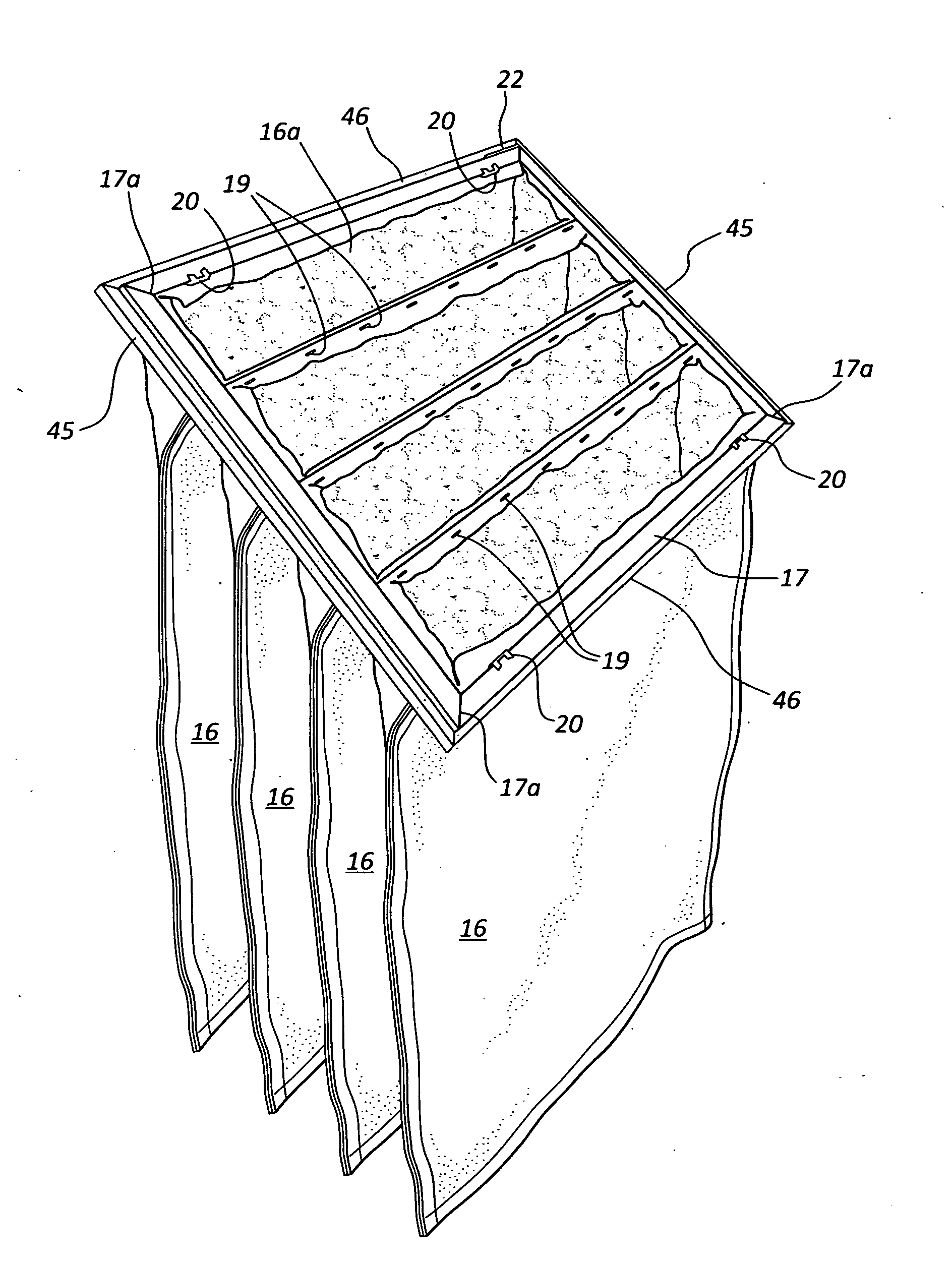
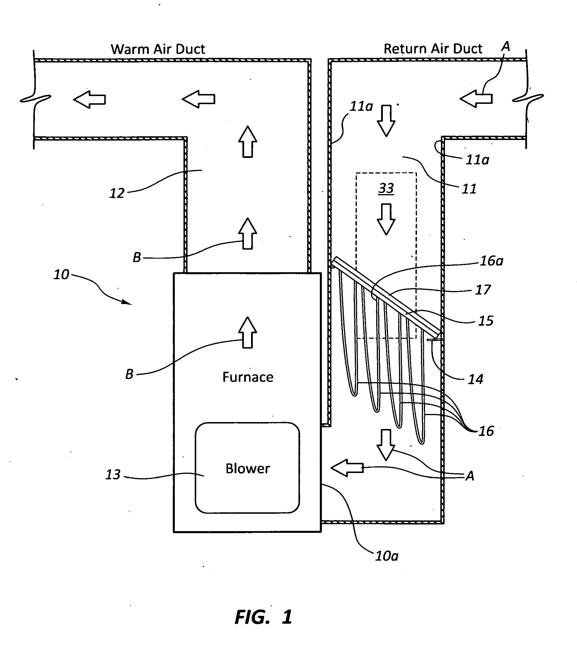
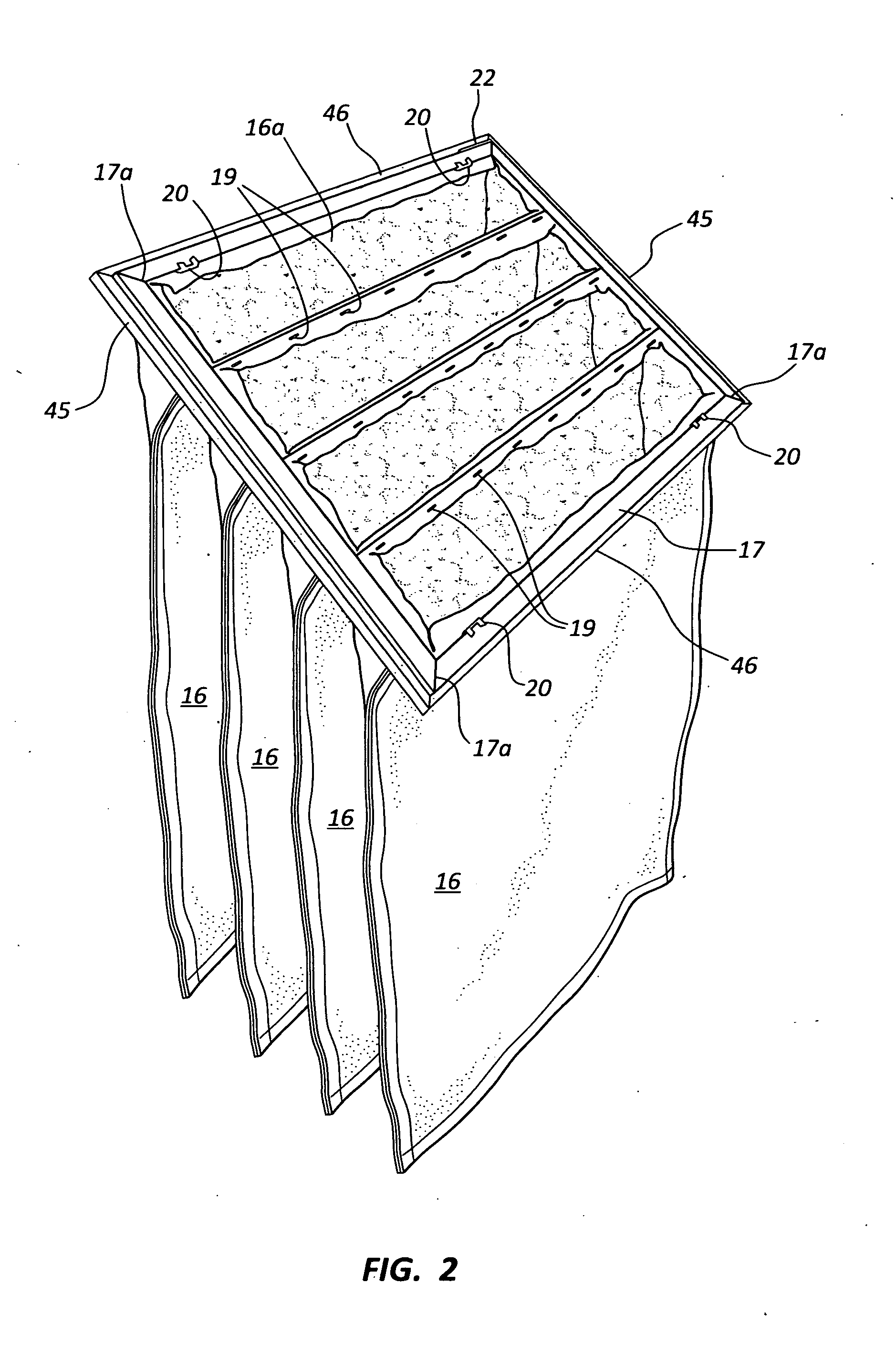
[0032]FIG. 1 shows a representation of a forced air furnace 10, hereinafter referred to as furnace, having an air inlet, or cold air return, and outlet ducts, 11 and 12, respectively. Arrows A represent air being pulled into the furnace by a blower 13, that heats air in the furnace and pushes that heated air, shown as arrows B, that travels through the outlet duct 12 to heat a dwelling. Earlier air filtration systems have generally employed flat rectangular filter elements that have been positioned across a furnace air inlet 10a, usually by sliding that filter element into a narrow opening, through the duct adjacent to the air inlet 10a. Such flat filters have provided dust collection to an inlet air flow whose effectiveness is governed by the surface area across the filter element. Recently, a number of flat waffle filter elements have come into common use with the peaks and valleys of the waffle surface providing an increase in the filter surface area of approximately fifty percen...


PUM

PropertyMeasurementUnit
Lengthaaaaaaaaaa
Angleaaaaaaaaaa
Lengthaaaaaaaaaa

Abstract

A bag filtration element and system for its installation in a forced air furnace where the filtration element includes a channel element frame that receives rectangular bag frames fitted thereto that each received an open bag neck end fitted thereto, and the rectangular bag frames are fitted side by side into the channel element frame, whose upper end closes the frame into a rectangle, and, the bag ends are folded around the bag frames sides and connected. A rectangular opening is formed into the plenum of a furnace inlet air duct to extend, at an upward angle, across the rectangular opening, between opposing inner walls of the air duct, and a door is provides for positioning over the duct rectangular opening with the bag filtration element installed therein.

Description

BACKGROUND OF THE INVENTION[0001]1. Field of the Invention[0002]This invention relates bag filters and their mountings for filtering return air of a forced air furnace system, with the return air duct as the housing for the system.[0003]2. Prior Art[0004]Return air filters for residential and commercial forced air heating and cooling units have traditionally been installed in the transition between the air handler and the termination of the return air duct. This tradition is typically a one inch filter rack installed between the air handler and the end of the duct, or inside the air handler, or some higher efficiency filters supply their own housing to hold their filter, which is installed between the air handler and the termination of the return air duct, which requires modification of the duct to allow for the housing to fit into the system.[0005]Return air filters for residential and commercial forced air furnaces have traditionally employed square or rectangular filters having a...

Claims


Application Information

Patent Timeline
IPC IPC(8): B01D46/02
CPCB01D46/02B01D46/0002B01D46/023
Inventor KEARSLEY, DOUGLAS I.
Owner KEARSLEY SUPERIOR FILTRATION
Why Eureka
Try Eureka