
Heat dissipating module

a technology of heat dissipation module and heat dissipation chamber, which is applied in the direction of indirect heat exchangers, light and heating apparatus, etc., can solve the problems of major barriers to the performance of electronic equipment and system improvement, and achieve the effect of enhancing the area of the heat pipe wick structure, enhancing the efficiency of the capillary channel of the heat pipe channel, and enhancing the supporting force between the first flat shell body and the second flat shell body

Active Publication Date: 2018-02-20
ASIA VITAL COMPONENTS SHENZHEN CO LTD
View PDF3 Cites 2 Cited by
  • Summary
  • Abstract
  • Description
  • Claims
  • Application Information

AI Technical Summary

Benefits of technology

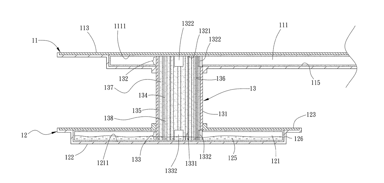
[0012]Another objective of the present invention is to provide a heat pipe whose pipe wall having an inner surface provided with a plurality of ribs disposed spacedly. A groove is disposed between each two adjacent ribs. The heat pipe wick structure is formed on the ribs and the grooves. Thus, the area of the heat pipe wick structure increases and the efficiency of the capillary channel of the heat pipe channel is enhanced.
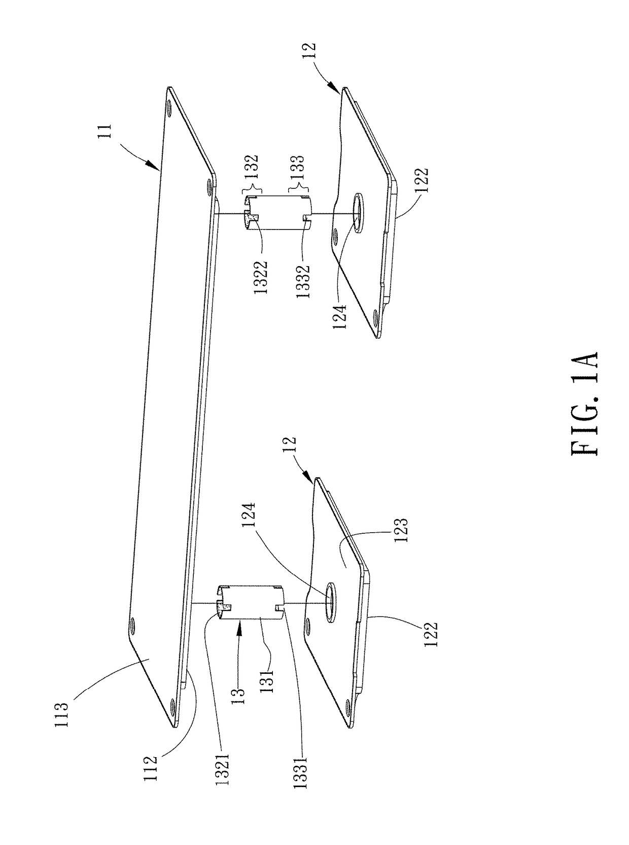
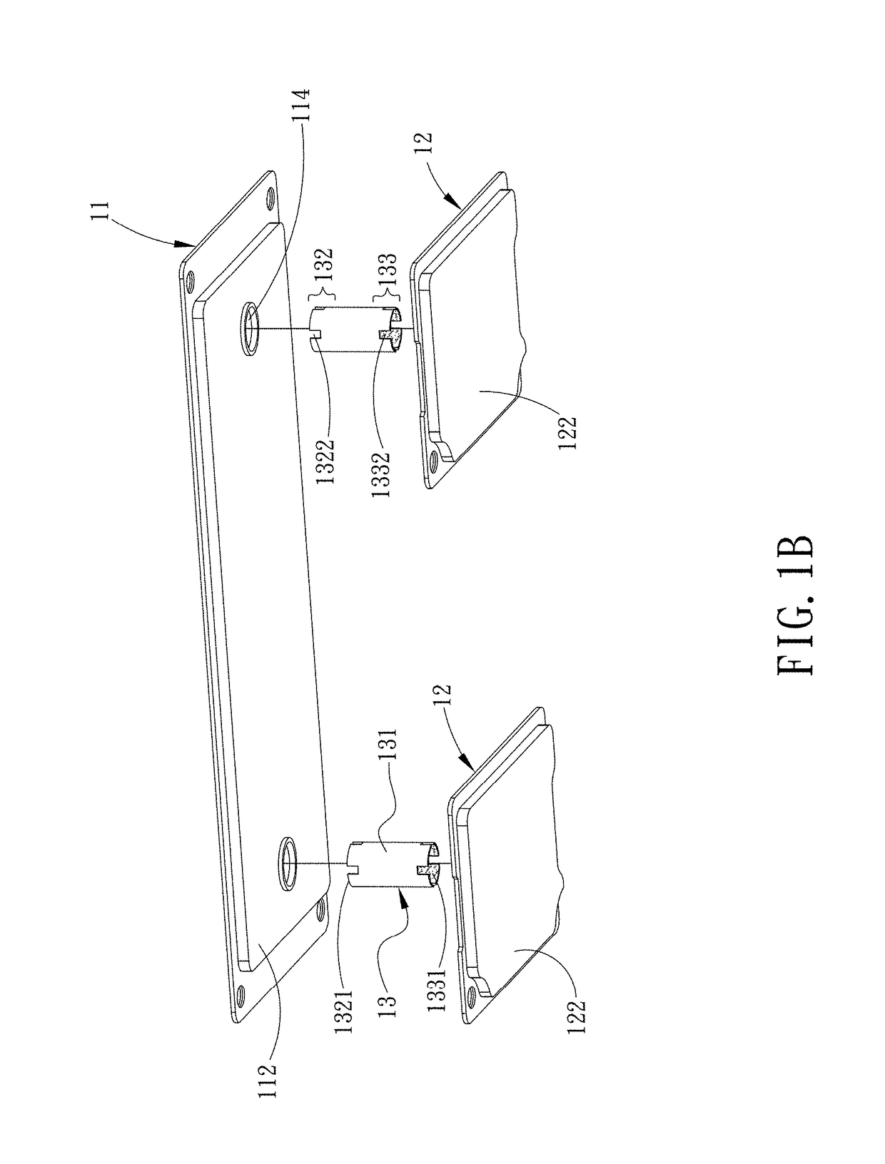
[0013]Another objective of the present invention is to provide a heat pipe channel of a heat pipe. A supporting cylinder is disposed in the heat pipe channel and a cylindrical wick structure is disposed on the outer surface of the supporting cylinder. Thus, the supporting force between the first flat shell body and the second flat shell bodies can be enhanced through the heat pipes and the supporting cylinders. Also, the reflow capillary paths between the first chamber and the second chambers can be improved through the heat pipe wick structure and the cylindrical wick structure.

Problems solved by technology

When the electronic equipment shrinks, the accompanying heat creates the major barrier to the performance of electronic equipment and system improvement.

Method used


Image

  • Heat dissipating module
  • Heat dissipating module
  • Heat dissipating module

Examples


Embodiment Construction

[0040]The above objectives, structural and functional characteristics of the present invention will be described according to the preferred embodiments in the accompanying drawings.

[0041]The present invention provides a heat dissipating module which comprises a first flat shell body and a plurality of second flat shell bodies. The first flat shell body has first chamber having a first wick structure formed on an inner wall of the first chamber. Each of the second flat shell bodies defines a second chamber. The second chamber has a working fluid and a second wick structure therein. Each of the second flat shell bodies is connected to and below the first flat shell body through a heat pipe. Each second chamber communicates with the first chamber through the corresponding heat pipe. The working fluid in each of the second chambers flows into the first chamber through the corresponding heat pipe to dissipate heat and then flows back to the second chamber through the corresponding heat p...


PUM


Abstract

The present invention relates to a heat dissipating module which comprises a first flat shell body and a plurality of second flat shell bodies. The first flat shell body has a first chamber and a first wick structure formed on an inner wall of the first chamber. Each of the second flat shell bodies defines a second chamber which is provided with a working fluid and a second wick structure therein. Each of the second flat shell bodies has a heat pipe plugged and connected to the first flat shell body. Therefore, the working fluid in each of the second chambers flows into the first chamber through the corresponding heat pipes to perform heat dissipation by liquid-vapor circulation.

Description

BACKGROUND OF THE INVENTIONField of the Invention[0001]The present invention relates to a heat dissipating module and in particular to a heat dissipating module which is used for heat dissipation.Description of Prior Art[0002]As the current electronic equipment gradually having compact and lightweight design to meet customers' requirements, the sizes of the electronic components thereof decrease accordingly. When the electronic equipment shrinks, the accompanying heat creates the major barrier to the performance of electronic equipment and system improvement. Therefore, to effectively deal with the problem of heat dissipation of the components in the electronic equipment, the industry proposes the vapor chamber and heat pipe which have better performance of heat transfer to solve the present issue of heat dissipation.[0003]The vapor chamber is a shell body (or planar body) having a rectangular shape. There are wick structures disposed on the chamber wall in the shell body and there ...

Claims


Application Information

Patent Timeline
Patent Type & Authority Patents(United States)
IPC IPC(8): F28D15/00F28D15/04
CPCF28D15/04F28D15/0233F28D15/0266F28D15/046F28D2021/0028
Inventor LAN, WEN-JI
Owner ASIA VITAL COMPONENTS SHENZHEN CO LTD
Learn More