Multi-axis electronic module mounting adjustment assembly

a technology of electronic modules and mounting brackets, which is applied in the direction of instruments, machine supports, building scaffolds, etc., can solve the problems of not being able to facilitate sufficiently accurate and precise alignment of stators, and suffering certain drawbacks, and achieve the effect of high precision, adequate accuracy and performan

Inactive Publication Date: 2013-01-03
HONEYWELL INT INC
View PDF7 Cites 0 Cited by
  • Summary
  • Abstract
  • Description
  • Claims
  • Application Information

AI Technical Summary

Benefits of technology

The patent describes a mounting assembly for adjusting the position of an electronic module along three perpendicular axes. The mounting assembly includes three adjustment blocks that move along the first, second, and third axes, respectively. The mounting assembly also includes a housing and a mounting bracket that are both mounted against movement and can be moved relative to each other. The mounting bracket is coupled to the stator, which is in wireless communication with the rotor element. The mounting assembly allows for precise positioning of the electronic module relative to the rotor element and can simultaneously adjust its position along the second and third axes. This results in a more accurate and efficient torque measurement system.

Problems solved by technology

However, it can suffer certain drawbacks.
For example, end-users typically provide their own mounting hardware for the stator, which may not facilitate sufficiently accurate and precise alignment of the stator.

Method used


Image

  • Multi-axis electronic module mounting adjustment assembly
  • Multi-axis electronic module mounting adjustment assembly
  • Multi-axis electronic module mounting adjustment assembly

Examples


Embodiment Construction

[0018]The following detailed description is merely exemplary in nature and is not intended to limit the invention or the application and uses of the invention. As used herein, the word “exemplary” means “serving as an example, instance, or illustration.” Thus, any embodiment described herein as “exemplary” is not necessarily to be construed as preferred or advantageous over other embodiments. All of the embodiments described herein are exemplary embodiments provided to enable persons skilled in the art to make or use the invention and not to limit the scope of the invention which is defined by the claims. Furthermore, there is no intention to be bound by any expressed or implied theory presented in the preceding technical field, background, brief summary, or the following detailed description.

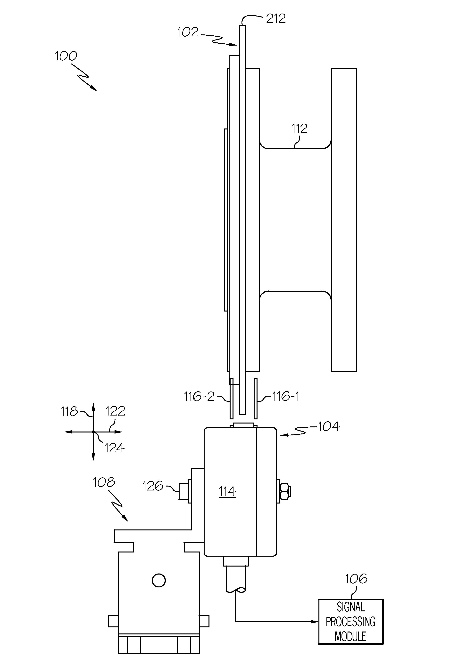
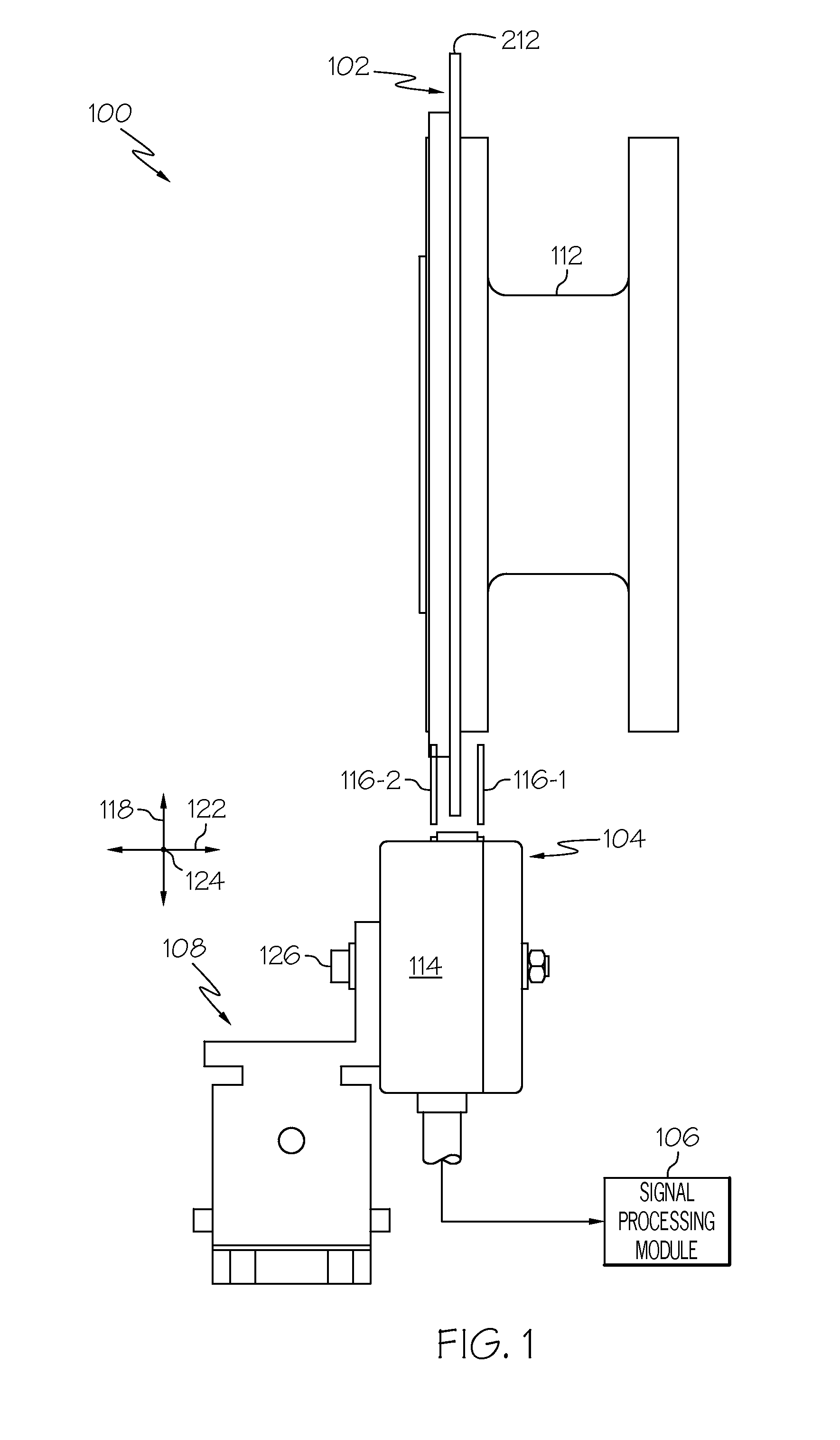
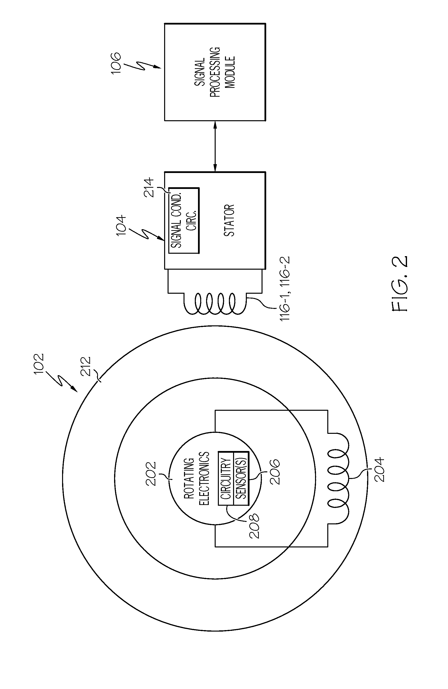
[0019]With the above in mind, it is noted that although embodiments are described as being implemented with a torque measurement system, the described embodiments may be implemented with any on...


PUM

PropertyMeasurementUnit
thicknessaaaaaaaaaa
volumeaaaaaaaaaa
torque measurementaaaaaaaaaa

Abstract

A mounting assembly for adjusting the position of an electronic module along a first axis, a second axis, and a third axis, in which the first, second, and third axes are all perpendicular to each other, includes a first adjustment block, a second adjustment block, and a third adjustment block. The first adjustment block is movable along the first axis and the second axis and is mounted against movement along the third axis. The second adjustment block is coupled to the first adjustment block, is movable along the second axis, and is mounted against movement along the first and third axes. The third adjustment block is disposed between the first adjustment block and the second adjustment block, is movable along the second and third axes, and is mounted against movement along the first axis.

Description

TECHNICAL FIELD[0001]The present invention generally relates to adjustable mounting assemblies, and more particularly relates to a multi-axis mounting adjustment assembly for an electronic module, such as a torque measurement system stator.BACKGROUND[0002]Numerous and varied methods have been derived for determining the torque on a rotating system. One example of a known torque measurement system includes a rotor element, a stator, and a signal processing module. The rotor element is mounted on a rotating shaft and thus rotates with the shaft. The rotor element is configured to sense one or more parameters representative of torque on the rotating shaft, and includes appropriate circuitry and an antenna that, among other things, transmits radio frequency (RF) signals representative of the one or more sensed parameters. The stator is mounted adjacent to the rotor element and includes one or more antennae. The stator, via the one or more antennae, receives the RF signals transmitted by...

Claims


Application Information

Patent Timeline
Patent Type & Authority Applications(United States)
IPC IPC(8): G01L3/14H05K7/00
CPCG01L3/04
Inventor YAGATI, VEERESH SHIVAPRAKASHRAMAMURTHY, GAUTHAMJARRELL, MAXESWARAN, SIVAPRAKASH
Owner HONEYWELL INT INC
Why Eureka
Try Eureka