Image-capturing device

Inactive Publication Date: 2013-01-03
PANASONIC INTELLECTUAL PROPERTY MANAGEMENT CO LTD
View PDF7 Cites 52 Cited by
  • Summary
  • Abstract
  • Description
  • Claims
  • Application Information

AI Technical Summary

Benefits of technology

[0030]According to the image-capturing device in the present invention, a color vi

Problems solved by technology

However, by removing the light in the infrared wavelengths as described above, a color image having good color reproducibility can be obtained when it is l

Method used


Image

  • Image-capturing device
  • Image-capturing device
  • Image-capturing device

Examples


embodiment 1

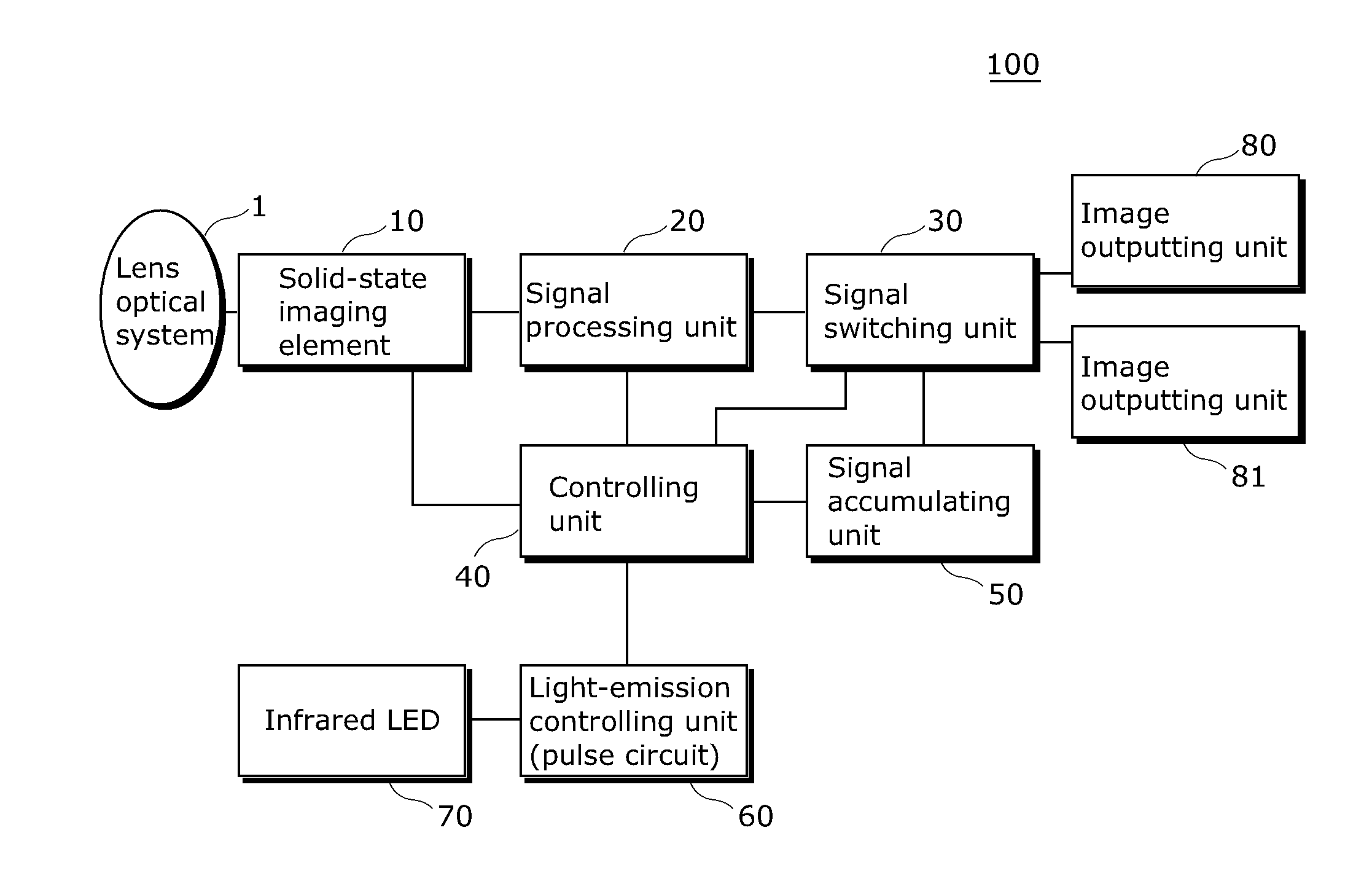
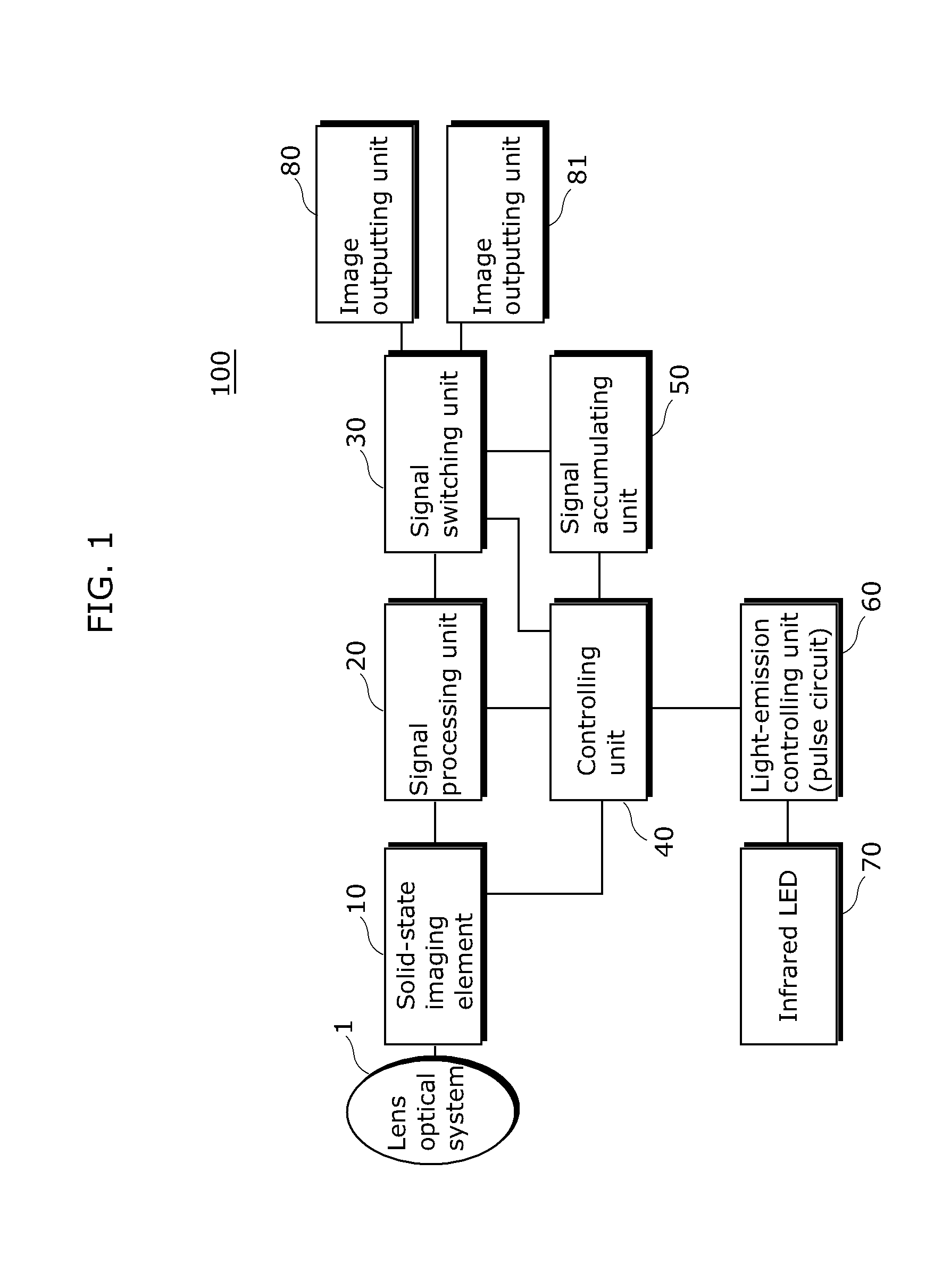
[0055]The following describes the structure of an image-capturing device (camera system) 100 according to Embodiment 1 of the present invention.

[0056]FIG. 1 is a function block diagram showing an image-capturing device according to Embodiment 1 of the present invention. The image-capturing device 100 illustrated in the drawing includes a lens optical system 1, a solid-state imaging element 10, a signal processing unit 20, a signal switching unit 30, a controlling unit 40, a signal accumulating unit 50, a light-emission controlling unit 60, an infrared LED 70 which is a light-emitting element emitting infrared light, and image outputting units 80 and 81. It should be noted that although a CMOS imaging sensor, for example, is used as the solid-state imaging element 10, it is not limited to the CMOS imaging sensor, and a CCD imaging sensor, for example, may also be used. It should also be noted that all or a part of the structure except the solid-state imaging element 10 and the lens o...

embodiment 2

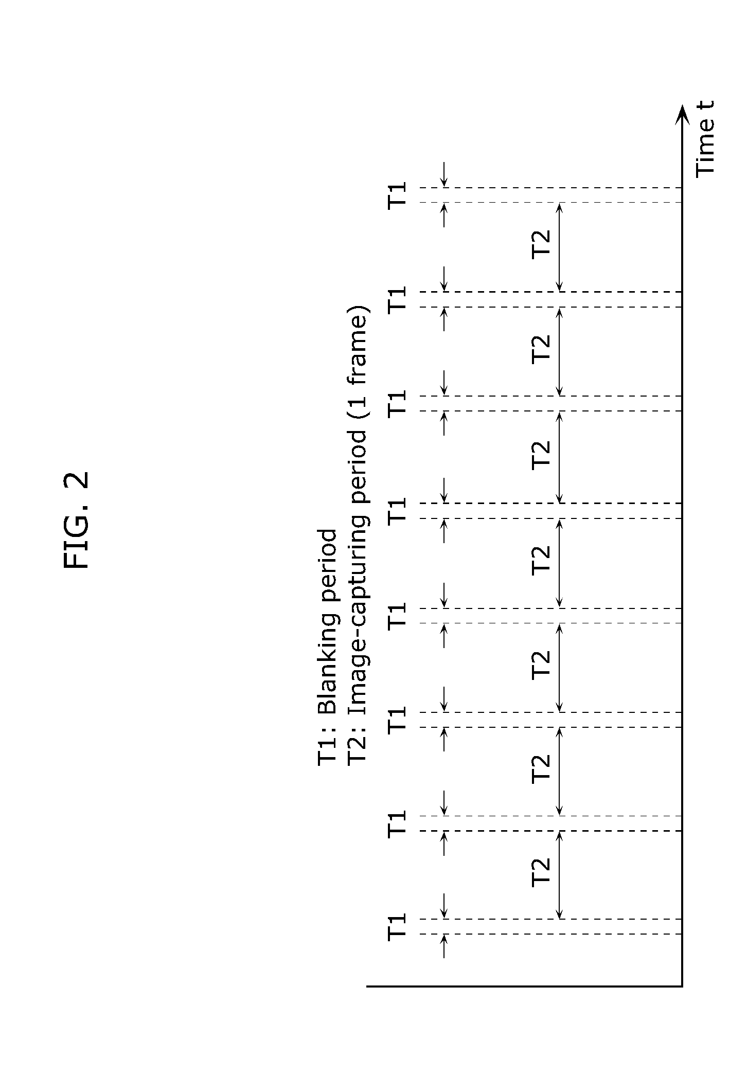
[0090]In an image-capturing device according to Embodiment 2 of the present invention, timing to drive the infrared LED 70 to emit pulsed light is different from that in Embodiment 1. The following mainly describes the timing to drive the infrared LED 70 to emit pulsed light, and the description of the same structure as that in Embodiment 1 is omitted.

[0091]The controlling unit 40 determines the timing to drive the infrared LED 70 to emit pulsed light based on the timing of a horizontal blanking period and the timing of an image-capturing period of one frame of the solid-state imaging element 10. Moreover, the infrared LED 70 emits the pulsed light in response to the driving pulse signal generated by the light-emission controlling unit 60.

[0092]FIG. 11 is a timing chart showing emission timing of the infrared LED 70 according to Embodiment 2 of the present invention. The infrared LED 70 is repeatedly turned ON or OFF in a pseudorandom manner. When turned ON, the infrared LED 70 star...


PUM


Abstract

The image-capturing device according to the present invention includes a solid-state imaging element, an infrared LED which emits infrared light, a light-emission controlling unit which causes the infrared LED to emit infrared pulsed light on a per frame time basis, and a signal processing unit which extracts, from the solid-state imaging element, a color visible-light image signal in synchronization with a non-emitting period and an infrared image signal in synchronization with an emitting period of the infrared LED. The solid-state imaging element includes an image-capturing region in which unit-arrays are two-dimensionally arranged, and each of the unit-arrays has a pixel for receiving green visible light and infrared light, a pixel for receiving red visible light and infrared light, a pixel for receiving blue visible light and infrared light, and a pixel for receiving infrared light.

Description

CROSS REFERENCE TO RELATED APPLICATIONS[0001]This is a continuation application of PCT Patent Application No. PCT / JP2010 / 005912 filed on Oct. 1, 2010, designating the United States of America, which is based on and claims priority of Japanese Patent Application No. 2010-100291 filed on Apr. 23, 2010. The entire disclosures of the above-identified applications, including the specifications, drawings and claims are incorporated herein by reference in their entirety.TECHNICAL FIELD[0002]The present invention relates to an image-capturing device which is capable of simultaneously outputting a color visible-light image and a monochrome infrared image.BACKGROUND ART[0003]Conventionally, a camera used in both nighttime and daytime such as a monitoring camera and a network camera uses solid-state imaging elements such as Charge Coupled Device (CCD) and Metal Oxide Semiconductor (MOS) sensors. Such solid-state imaging elements have sensitivity in a wavelength range of approximately 400 nm to...

Claims


Application Information

Patent Timeline
IPC IPC(8): H04N5/335H04N5/33
CPCH04N5/2353H04N5/2354H04N9/045H04N5/332G01S17/87G01S17/89G01S7/4863H04N2209/045H04N23/73H04N23/74H04N23/11H04N25/131H04N25/135
Inventor ONOZAWA, KAZUTOSHIKATO, YOSHIHISAKOUYAMA, SHINZOU
Owner PANASONIC INTELLECTUAL PROPERTY MANAGEMENT CO LTD
Why Eureka
Try Eureka