

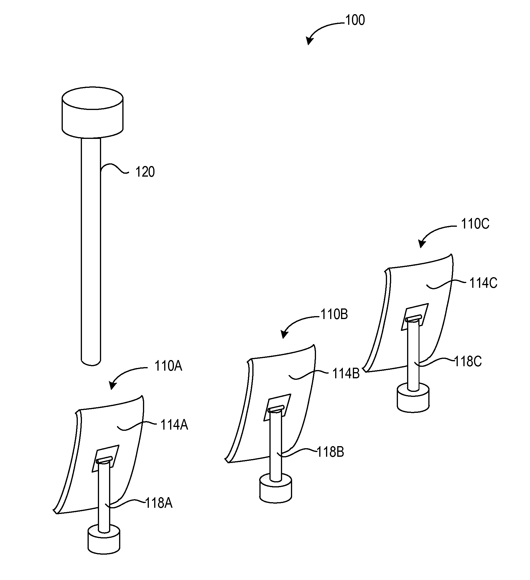
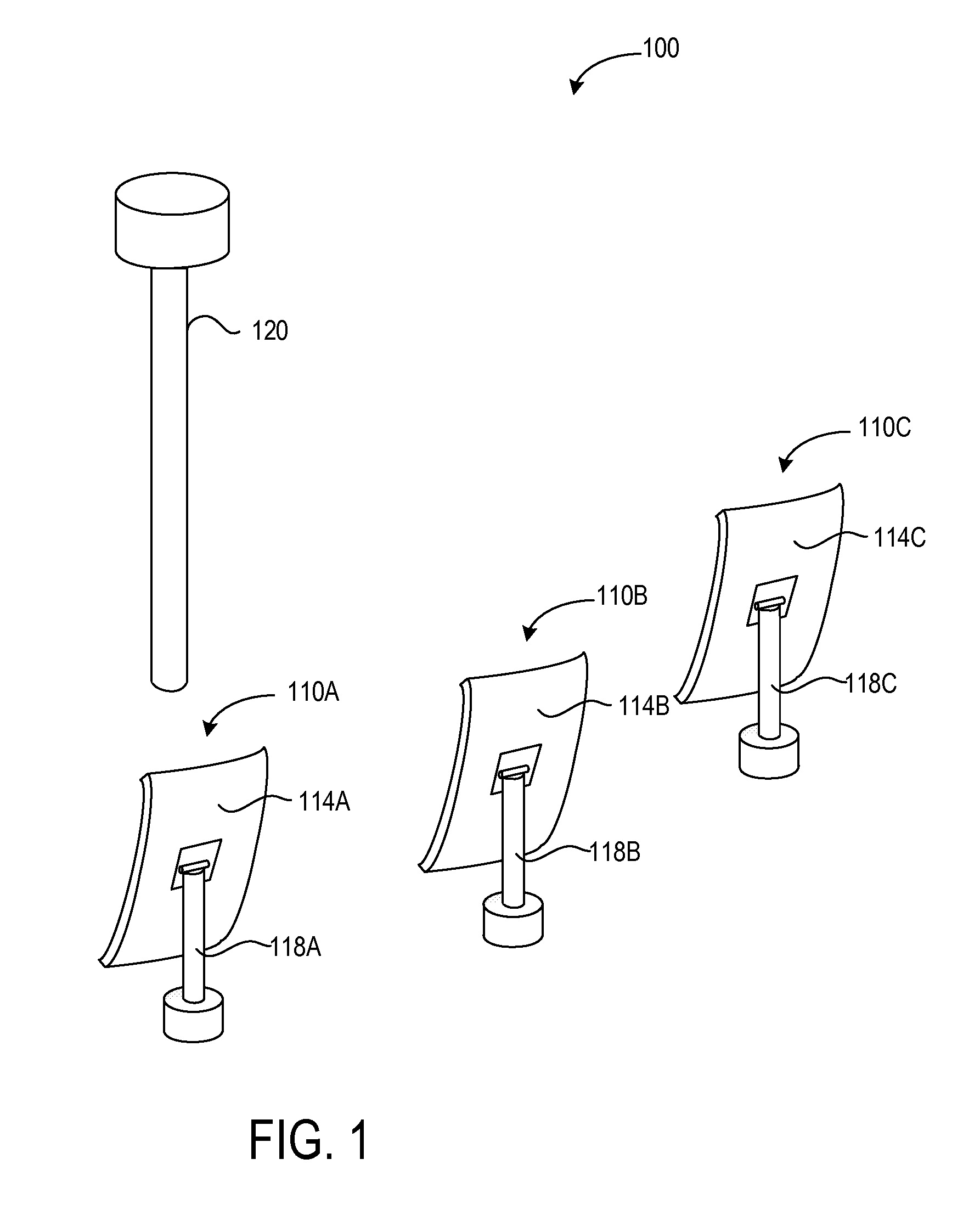
Heliostat mirror with supporting rib structure
a technology of heliostat mirror and supporting rib, which is applied in the safety of solar heat collectors, instruments, lighting and heating apparatuses, etc., can solve the problems of heliostat mirror deformation or cracking, reflective surface deformation, and lower overall efficiency of solar power generation systems
- Summary
- Abstract
- Description
- Claims
- Application Information
AI Technical Summary
Benefits of technology
Problems solved by technology
Method used
Image

Examples
Embodiment Construction
[0030]The Figures (FIG.) and the following description relate to preferred embodiments of the present invention by way of illustration only. It should be noted that from the following discussion, alternative embodiments of the structures and methods disclosed herein will be readily recognized as viable alternatives that may be employed without departing from the principles of the claimed invention.
[0031]Reference will now be made in detail to several embodiments of the present invention(s), examples of which are illustrated in the accompanying figures. It is noted that wherever practicable, similar or like reference numbers may be used in the figures and may indicate similar or like functionality. The figures depict embodiments of the present invention for purposes of illustration only.
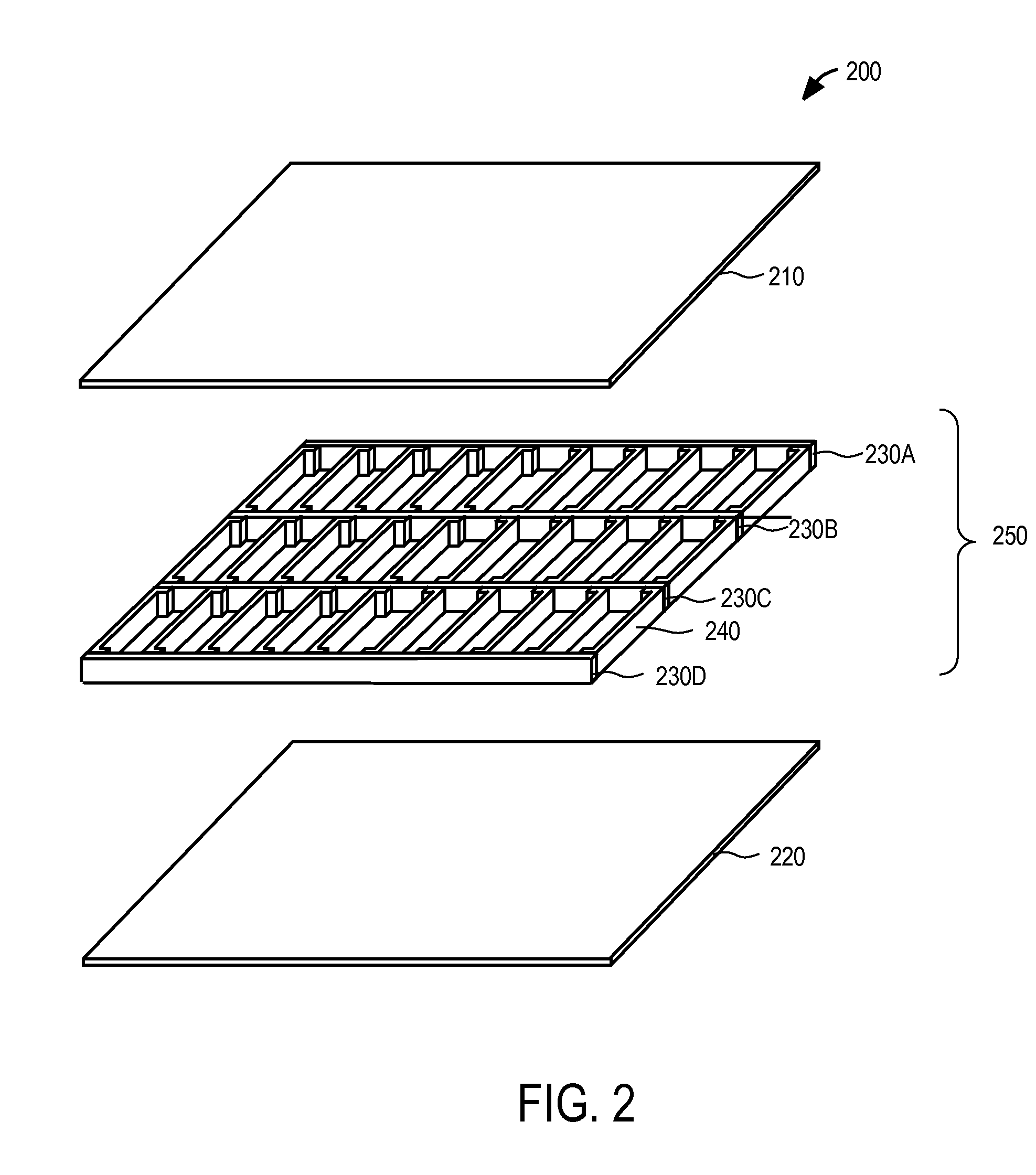
[0032]Embodiments relate to a mirror module including one or more rib elements made of material having the same or similar coefficient of thermal expansion as a rear plate and / or front plate. The rib ...
PUM
 Abstract
Description
Claims
Application Information