

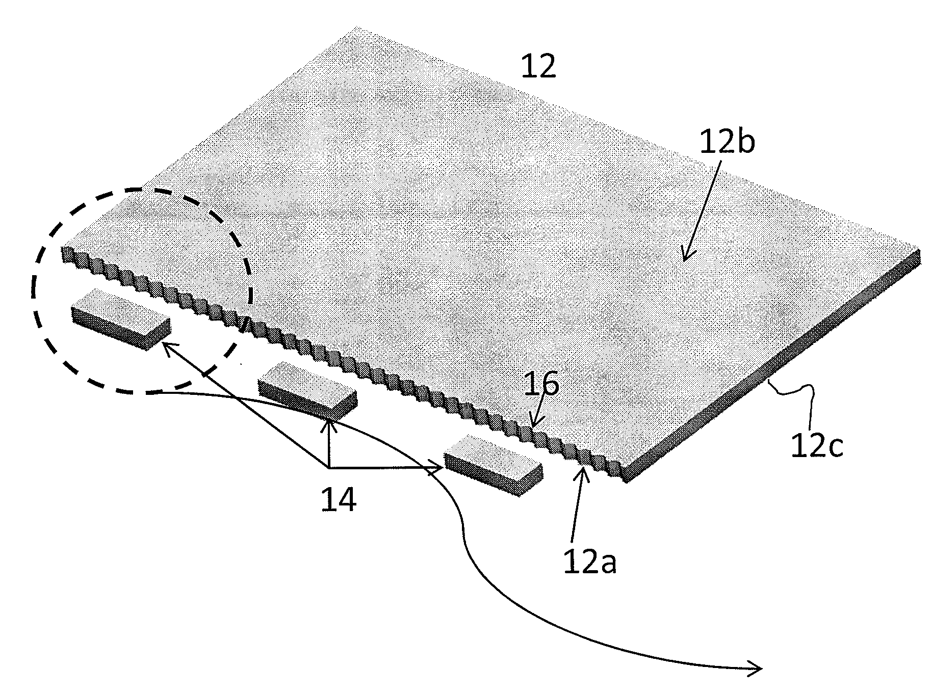
Symmetric serrated edge light guide film having circular tip and base segments
a light guide film and symmetric serration technology, which is applied in the direction of lighting apparatus, lighting device details, lighting and heating apparatus, etc., can solve the problems of limited light diffusing capability of continuous prism or arc-shaped structures on the input surface, and achieve uniform surface illumination without sacrificing the efficiency of the backlight system
- Summary
- Abstract
- Description
- Claims
- Application Information
AI Technical Summary
Benefits of technology
Problems solved by technology
Method used
Image

Examples
examples
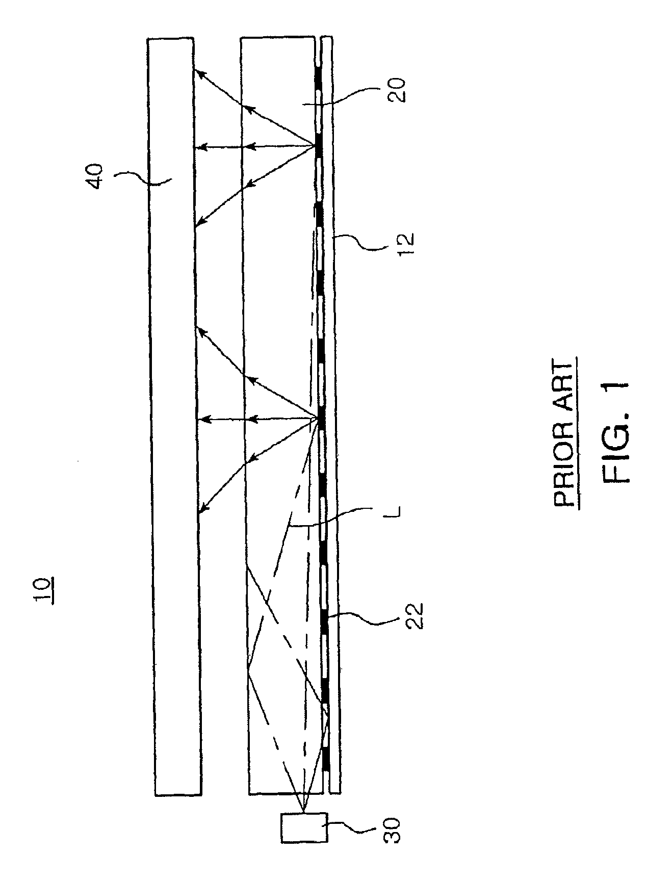
[0043]FIG. 9a shows a portion of the light input surface 32 of a light guide film 30 with an arc- or circular-type structure 36. The graph in FIG. 9b illustrates the light intensity for the light guide film 30 at distances 3.5 mm, 4.5 mm and 5.5 mm from the light input surface 32. FIG. 9b shows that the localized light intensity decreases as the distance increases from the light input surface, but there are still some hot spots evident at 5.5 mm. The arc- or circular-type structure solution provides some improvement for hot spots but is more effective at collimating light in line with the LED than widening the incidence angle. This is evident in the graph in FIG. 9b. In FIG. 9b, the LEDs are located at each of the vertical dotted lines and the light distribution is still not leveled out at 5.5 mm into the light guide film. It is apparent from the graph in FIG. 9b that the arc- or circular-type solution has insufficient diffusion capability.
[0044]FIG. 10a shows a portion of the light...
PUM
 Abstract
Description
Claims
Application Information