X-ray analysis apparatus with radiation monitoring feature

a radiation monitoring and x-ray technology, applied in the field of x-ray devices, can solve the problems of affecting the normal use of instruments, and the design of shields can be bulky, so as to reduce radiation levels and add weight

Active Publication Date: 2013-01-03
OLYMPUS AMERICA
View PDF8 Cites 27 Cited by
  • Summary
  • Abstract
  • Description
  • Claims
  • Application Information

AI Technical Summary

Benefits of technology

[0005]Some portable XRF devices have been introduced with an external shield over the end of the unit, where the x-rays are emitted. While this shielding does reduce radiation levels external to the device, compared to with the external shield removed, using an external shield has a number of disadvantages. Shielding can be misplaced or may be removed from the instrument by the user. Some shield designs can also be bulk

Problems solved by technology

Some shield designs can also be bulky and interfere with normal usage of the instrument especially when testing smaller samples.
It may be hard to position the portable XRF device so that the desired area of a sample is being irradiated.
Shields also generally add weight to the XRF instrument, and negatively impact the ergonomics, making them “end heavy” and unbalanced since

Method used


Image

  • X-ray analysis apparatus with radiation monitoring feature
  • X-ray analysis apparatus with radiation monitoring feature
  • X-ray analysis apparatus with radiation monitoring feature

Examples


Embodiment Construction

[0019]Aside from the preferred embodiment or embodiments disclosed below, this invention is capable of other embodiments and of being practiced or being carried out in various ways. Thus, it is to be understood that the invention is not limited in its application to the details of construction and the arrangements of components set forth in the following description or illustrated in the drawings. If only one embodiment is described herein, the claims hereof are not to be limited to that embodiment. Moreover, the claims hereof are not to be read restrictively unless there is clear and convincing evidence manifesting a certain exclusion, restriction, or disclaimer.

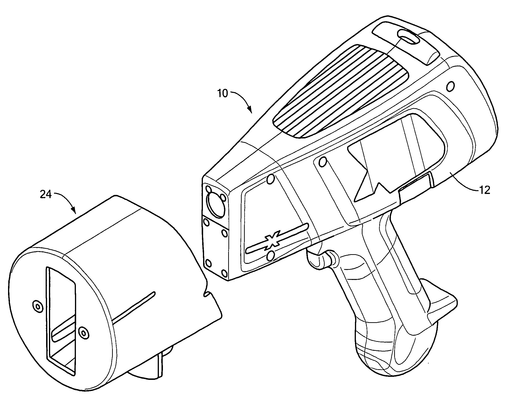
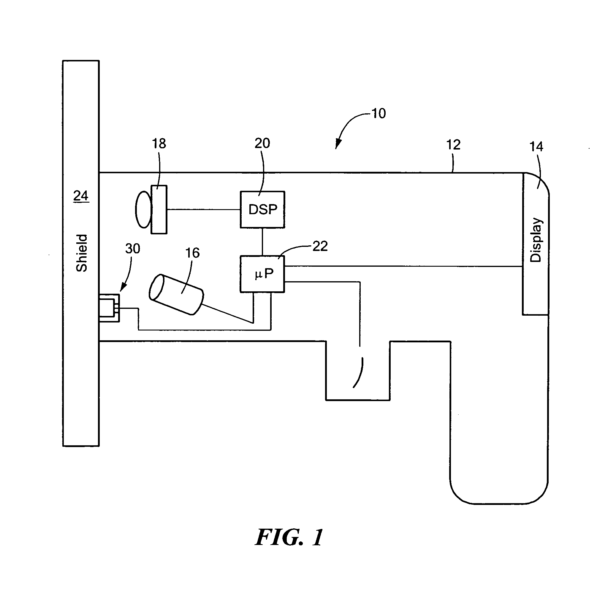
[0020]FIG. 1 shows an example of an x-ray analysis apparatus, in this particular example, a handheld “open beam” XRF instrument 10 including gun shaped housing 12 with display 14 and containing, inter alia, x-ray source 16 and detector 18 with digital signal processing subsystem 20 which analyzes radiation detected by detec...


PUM


Abstract

An XRF analysis apparatus includes a housing with a source of penetrating radiation to be directed at a sample and a detector for detecting fluoresced radiation from the sample. A shield is attachable to the housing to protect the user from radiation and a safety interlock is configured to detect whether or not the shield is attached to the housing. A controller is responsive to the safety interlock, and configured to monitor usage of the source of radiation at or above a predetermined power level when the shield is not attached to the housing and provide an output signal when the monitored usage of the source of penetrating radiation at or above the predetermined power level without the shield attached to the housing exceeds one or more predetermined thresholds.

Description

FIELD OF THE INVENTION[0001]The subject invention relates to x-ray devices.BACKGROUND OF THE INVENTION[0002]X-ray devices such as handheld x-ray fluorescence (XRF) instruments are known as are various shields for such instruments. See U.S. Pat. Nos. 7,430,274; 7,375,359; 7,375,358; 6,965,118; and 7,671,350 as well as WO 00 / 37928 all incorporated herein by this reference. See also U.S. Published Application No. US-2008-0152079.[0003]The shields for these devices, typically attached to the nose of the instrument, serve to protect the user of the device from radiation. Radiation limits are usually established by regulations which may vary by jurisdiction.[0004]For handheld XRF devices with lower power x-ray tubes (e.g., below about 4 watts and producing about 40 keV), reaching a radiation limit is not as big a concern as with higher power x-ray tubes (e.g., those producing 50 keV and above) used in some industries. This is because at tube voltages of 50 kV and higher, a greater amount ...

Claims


Application Information

Patent Timeline
IPC IPC(8): G01N23/223H05G1/38
CPCG01N2223/076G01N23/223
Inventor SACKETT, DON
Owner OLYMPUS AMERICA
Why Eureka
Try Eureka