Powershift transmission in a motor vehicle

a technology for transmissions and motor vehicles, applied in the field of transmissions, can solve the problems of power transfer interruptions at gear shifts, power loss at gear shifts, turbo-charged diesel engines, etc., and achieve the effects of high reduction ratio, high range gears, and high power loss

Active Publication Date: 2013-01-03
VOLVO LASTVAGNAR AB
View PDF1 Cites 33 Cited by
  • Summary
  • Abstract
  • Description
  • Claims
  • Application Information

AI Technical Summary

Benefits of technology

[0019]U.S. Pat. No. 6,958,028B2, FIG. 5, shows a dual clutch transmission with a planetary range section. This transmission is similar to the one in U.S. Pat. No. 7,070,534B2. The main difference is that both input shafts, 30 and 40, use the same countershaft 50, tooth clutch 130, and gearwheels 122, 132 and 132, 128 between this countershaft and the planetary range section. Power interruption between low and high range gears is eliminated by a bridge torque path via a separate countershaft 152. That makes the transmission wide, and it shares the rest of the disadvantages of the one in U.S. Pat. No. 7,070,534B2; many components, long, and high power losses for high range gears.
[0020]FIG. 1 in US2008/0188342A1 shows a dual clutch transmission with one countershaft and a planetary range section. A bridge torque path is formed by a tooth clutch 84 that rotationally locks a loose gearwheel 64 on main shaft 28 to a planet carrier 68 rotationally fixed to output shaft 70. When power is led in this path, the gearwheels in the ...

Problems solved by technology

Because of the mechanical tooth clutches, there will during the shift be an interruption of the power transfer between the engine and the driven wheels of the vehicle.
Still, there will be power transfer interruptions at gear shifts.
Most heavy vehicles have turbo-charged diesel engines that have slow dynamic response.
Then, the power interruptions at gear shifts will have an unfavourable impact on the performance of the vehicle.
That makes them expensive, and they have considerable power losses.
Thereby, they are not suited for vehicles of the future, where fuel consumption will be more important than ever.
That may lead to difficulties in installing the transmission into the vehicle.
The number of gears and the corresponding speed reduction ratios are insufficient for heavy severe-duty vehicles, though.
These concepts are hence less suited to heavy vehicles.
Unfortunately, there are shifts between consecutive gears where the power transfer will be interrupted in these designs.
Therefore, they are not favourable from an installation point of view, and not with respect to vehicle performance.
However, for reasonable sizes of this friction clutch, the power transferred to the driven wheels is very small at shifts between low gears.
Thus, these types of dual clutch transmission would have a limited practical use, especially for on- and off-road vehicles.
This would probably be acceptable on most heavy on-road vehicles, bu...

Method used


Image

  • Powershift transmission in a motor vehicle
  • Powershift transmission in a motor vehicle
  • Powershift transmission in a motor vehicle

Examples


Embodiment Construction

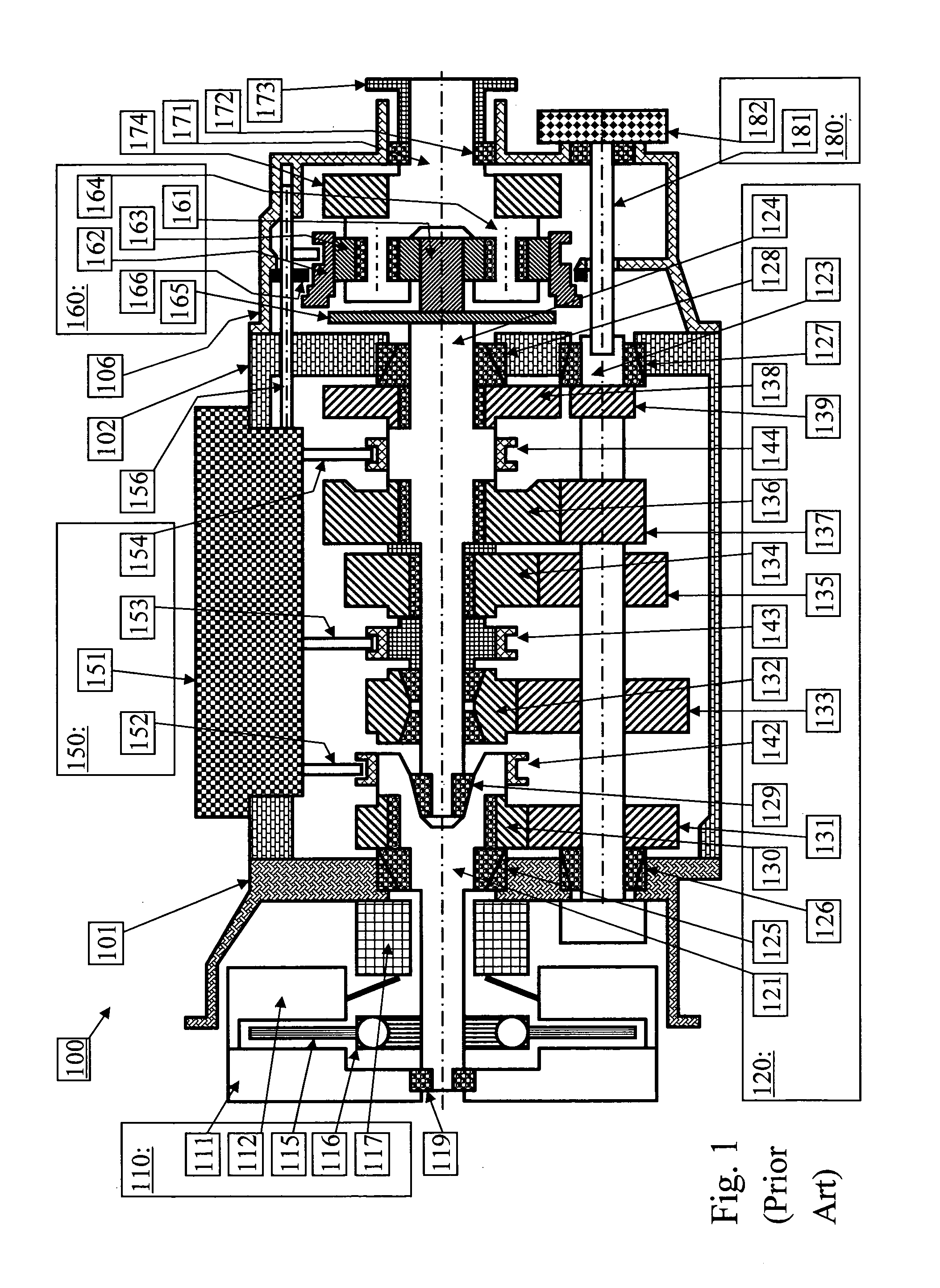
[0041]FIG. 1 shows schematically a longitudinal section of a stepped automatic mechanically engaged transmission (AMT) 100 according to known art for a heavy road vehicle. The transmission 100 comprises three housing parts; a clutch housing 101, a main housing 102 and a range housing 106. In the clutch housing 101 a frictional clutch 110 is arranged, comprising a flywheel 111, a clutch assembly 112 bolted thereon, a clutch disc 115 with torsional damper 116 and a clutch actuator 117. The flywheel III is attached to the engine crankshaft (not shown).

[0042]A main transmission 120 is arranged inside the main housing 102. There are three shafts in the main transmission 120; an input shaft 121, a countershaft 123 and a main shaft 124. The input shaft 121 and the main shaft 124 are coaxial, and the countershaft 123 is arranged parallel to them. The input shaft 121 is suspended in the clutch housing 101 by an input shaft bearing 125 and in the flywheel 111 by a flywheel pilot bearing 119. ...


PUM


Abstract

A powershift transmission in a motor vehicle is arranged between a prime mover and driven wheels of the motor vehicle for transmission of propulsive power and selection of different gear speed ratios. The powershift transmission includes at least two factional clutches for alternatively engaging at least two input shafts, a main transmission, a range section and an output shaft. A countershaft in the powershift transmission is rotationally connectable to the output shaft in order to establish a by-pass torque path, passing by the range section, and in which propulsive power can be transferred when the range section is gear shifted between different range speed ratios.

Description

BACKGROUND AND SUMMARY[0001]The present invention relates to vehicle transmissions, especially for heavy, on- as well as off-road vehicles, and more particularly to dual clutch transmissions with a range section that can be by-passed to allow it to be shifted without interrupting the power transfer.[0002]The conventional stepped transmission for rear-wheel drive vehicles can be regarded as a robust, compact and cost-effective product. A typical example of such a lay-out is shown in FIG. 2 in DE10242823 A1. An input shaft is coaxial with a main (output) shaft and parallel with a countershaft. A gearwheel that is rotationally fixed on the input shaft meshes with a gearwheel that is rotationally fixed on the countershaft. Several pairs of meshing gearwheels are then located side by side. In each of these pairs, one gearwheel is coaxial with the countershaft; the other is coaxial with the main shaft. One of these gearwheels is rotationally fixed on its coaxial shaft. The other gearwheel...

Claims


Application Information

Patent Timeline
IPC IPC(8): F16H37/06F16H3/091
CPCF16H3/006F16H37/046Y10T74/19051F16H2061/0429F16H2061/0425
Inventor HEDMAN, ANDERSSTALBERG, DANIEL
Owner VOLVO LASTVAGNAR AB
Why Eureka
Try Eureka