Eureka AIR delivers breakthrough ideas for toughest innovation challenges, trusted by R&D personnel around the world.

Drill bit

Inactive Publication Date: 2013-01-03
CPL HLDG
View PDF22 Cites 9 Cited by
  • Summary
  • Abstract
  • Description
  • Claims
  • Application Information

AI Technical Summary

Benefits of technology

The patent describes a design for a plant that has land and flutes where air flows. The land is curved and blends smoothly into the flute wall, which helps the air flow smoothly through the plant. This design helps the plant to work more efficiently.

Problems solved by technology

This results in an increase of pressure within the flutes which may result in the drill bit ceasing to function properly.
Typical drill bit designs are also inefficient at passing the swarf material into the flutes, causing a build up of swarf material in the reliefs at the operating end of the drill bit, thus reducing its efficiency.

Method used


Image

  • Drill bit
  • Drill bit
  • Drill bit

Examples


Embodiment Construction

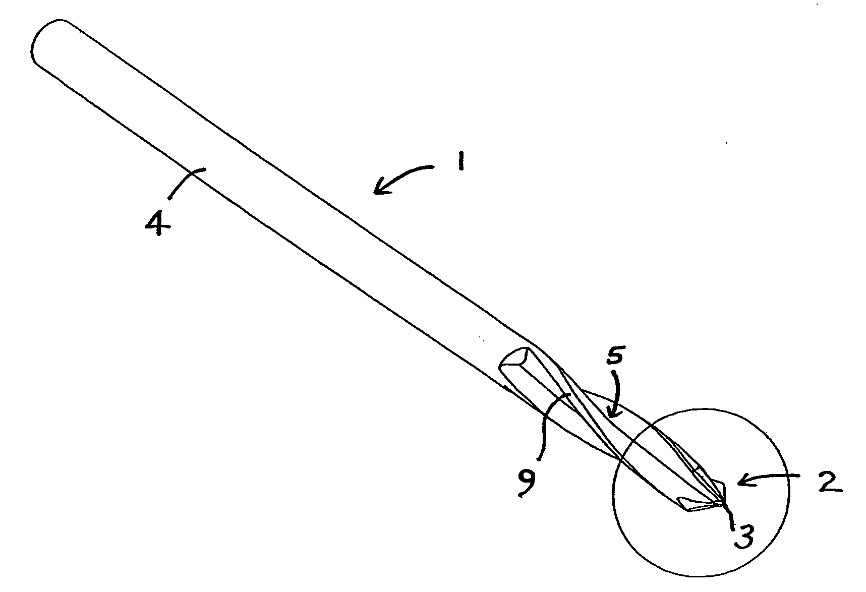
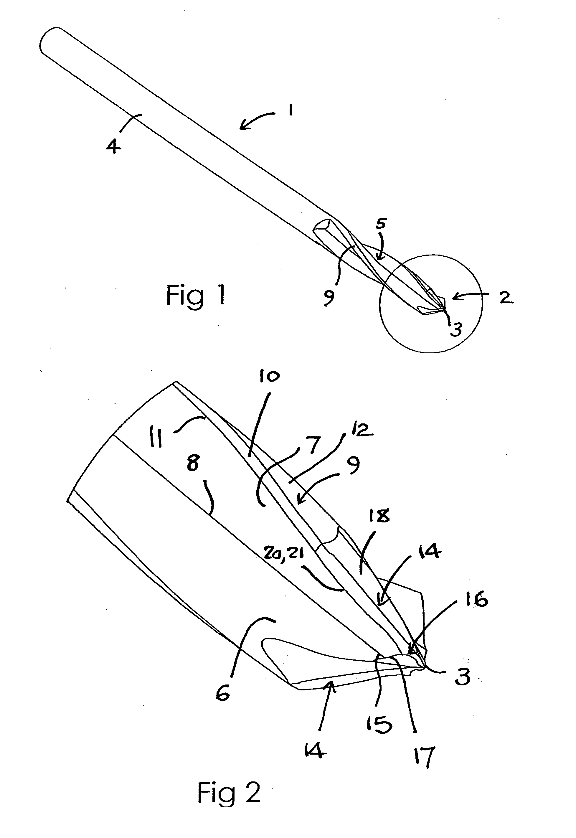
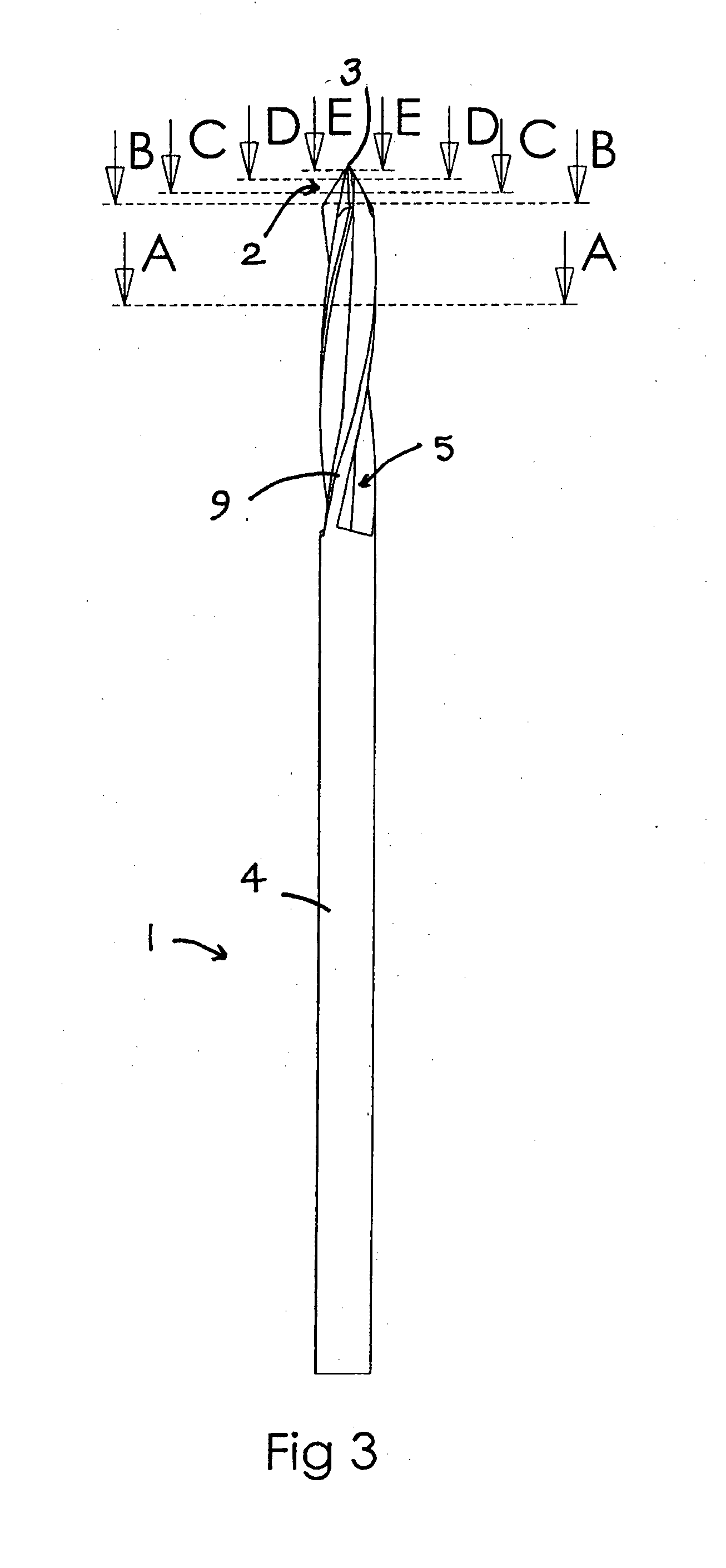
[0061]Referring to the accompanying drawings, a drill bit 1 has a tapered cutting end part 2 terminating in a drill tip 3 at a front, operative end of the drill bit 1, with a shank 4 extending from an opposing rear end of the drill bit 1. The shank 4 is configured to be received within the chuck of a drill in the usual way, and will typically be cylindrical although it may be hexagonal in cross-section or any other suitable shape. A plurality of flutes 5 are formed in the drill bit 1. In the embodiment depicted there are three flutes 5 that each extend from adjacent the shank 4 into the cutting end part 2. Each of the flutes 5 extends into the cutting end part 2 towards the drill tip 3, but finishes just short of the drill tip 3 as a result of the tapering of the cutting end part 2.

[0062]In the embodiment depicted, the drill bit 1 is configured to be rotated in a clockwise direction when viewed from the rear of the drill bit 1. Throughout this specification, various features of the ...


PUM

PropertyMeasurementUnit
Fractionaaaaaaaaaa
Angleaaaaaaaaaa
Diameteraaaaaaaaaa

Abstract

A drill bit (1) having a central axis (A) has a tapered cutting end (2) part terminating in a drill tip (3) at one end of the drill bit (1) and a shank (4) extending from an opposing end of the drill bit (1). A plurality of flutes (5) are formed in the drill bit (1) and helically extend from adjacent the shank (4) into the cutting end part (2). Each flute (5) has a flute leading side wall (6) and a flute trailing side wall (7) and a land (9) defined between each of the flutes (5) and extending to the tapered cutting end part (2). Each land (9) has a leading land margin (10) defining a secondary cutting edge (11) with the flute trailing side wall (7) of a leading adjacent flute (5). Each land (9) also has a land relief (12) extending from the land margin (10) toward a trailing adjacent flute (5). Each land (9) still further has a land transition region (12) blending the land relief (12) into the flute leading side wall (6) of the trailing adjacent flute (5). In any cross sectional plane extending perpendicular to the central axis (A) through the lands (9), the land margin (10) of each land (9) lies on a circle (B) extending about the central axis (A) and each relief (12) and each land transition region (13) lies entirely within the circle (B).

Description

TECHNICAL FIELD[0001]The present invention relates to the field of drill bits and in particular relates to, but is not limited to an orthopaedic drill bit.BACKGROUND OF THE INVENTION[0002]Drill bits are traditionally formed from a rod / shaft of high strength metallic material by grinding two or more helical galleys, known as flutes, into the side wall of the rod extending from the operative front end of the rod towards the rear end, leaving a cylindrical shank at the rear end of the rod. The flutes are separated by lands that define the full diameter of the rod. To reduce the drag that would otherwise be experienced between the lands and the wall of the hole being drilled, the trailing region of each of the lands is ground in a second operation, providing a slightly reduced diameter over this portion of the drill bit known as a relief. This leaves only a leading portion, known as a margin of the land, defining the full diameter of the drill. The leading edge of the margin defines a s...

Claims


Application Information

Patent Timeline
IPC IPC(8): A61B17/16B24B19/04
CPCA61B17/1615A61B17/16B23B51/02
Inventor ELLIS, LIAM PATRICK
Owner CPL HLDG
Why Eureka
Eureka Blog
Learn More