
Integrated prosthetic element

a prosthetic element and integrated technology, applied in the field of integrated prosthetic elements, can solve the problems of reducing the possibility of keeping in storage a series of inserts of a suitable shape and size, and it is necessary to control the heating level carefully, so as to facilitate the casting process into the porous structur

Active Publication Date: 2013-01-03
LIMA CORPORATE SPA
View PDF100 Cites 19 Cited by
  • Summary
  • Abstract
  • Description
  • Claims
  • Application Information

AI Technical Summary

Benefits of technology

The present invention is about an integrated prosthetic element that can be used for bone implant operations. It consists of a metal support and a plastic insert made of plastic material, which is coupled with the metal support. The plastic insert has cavities or holes distributed in a substantially uniform manner and a layer of porous structure on the opposite surface of the metal support. The plastic material is fed into the cavities or holes of the solidarization layer and then solidified to form the plastic insert. The integrated prosthetic element has improved bone anchoring and can be used for bone replacement or implant operations. The method for producing the integrated prosthetic element involves making the metal support and then feeding or casting the plastic material into the cavities or holes of the solidarization layer until it reaches the compact layer.

Problems solved by technology

One disadvantage of this solution is that it is necessary to control carefully the level of heating and of penetration of the plastic insert into the metal support, because the pores must not be completely filled since these are required for the process of osteo-integration after the implant.
Another disadvantage of this type of prosthetic element is that it is necessary to make the plastic insert in advance in the desired form, which entails additional operations, and also reduces the possibility of keeping in store a series of inserts of a suitable shape and size.

Method used


Image

  • Integrated prosthetic element
  • Integrated prosthetic element
  • Integrated prosthetic element

Examples


Embodiment Construction

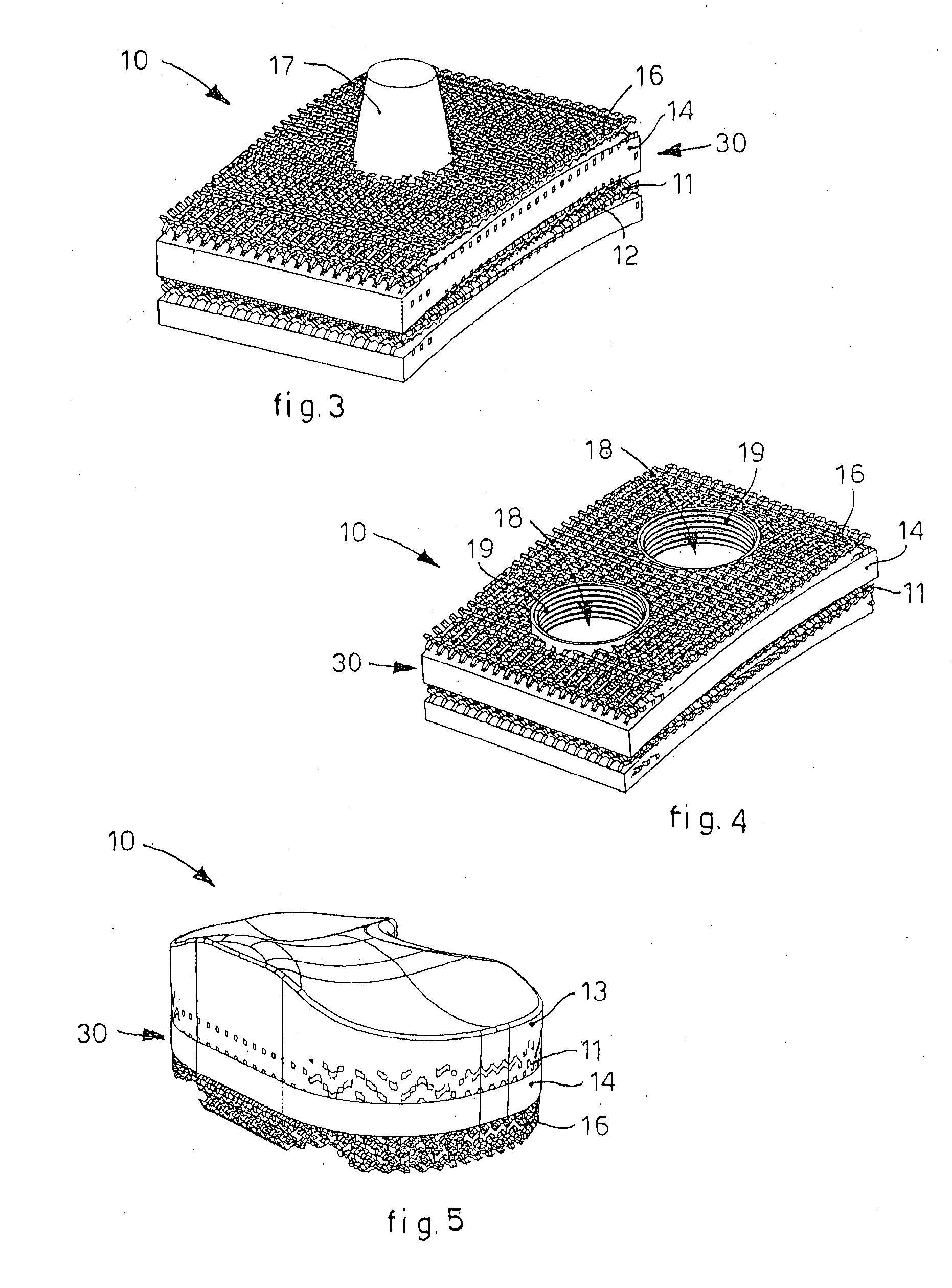
[0044]In the drawings to which reference will be made for the description of some forms of embodiment, the functional parts that perform the same functions have the same reference numbers. In particular, an integrated prosthetic element according to the present invention is denoted in its entirety by the reference number 10.

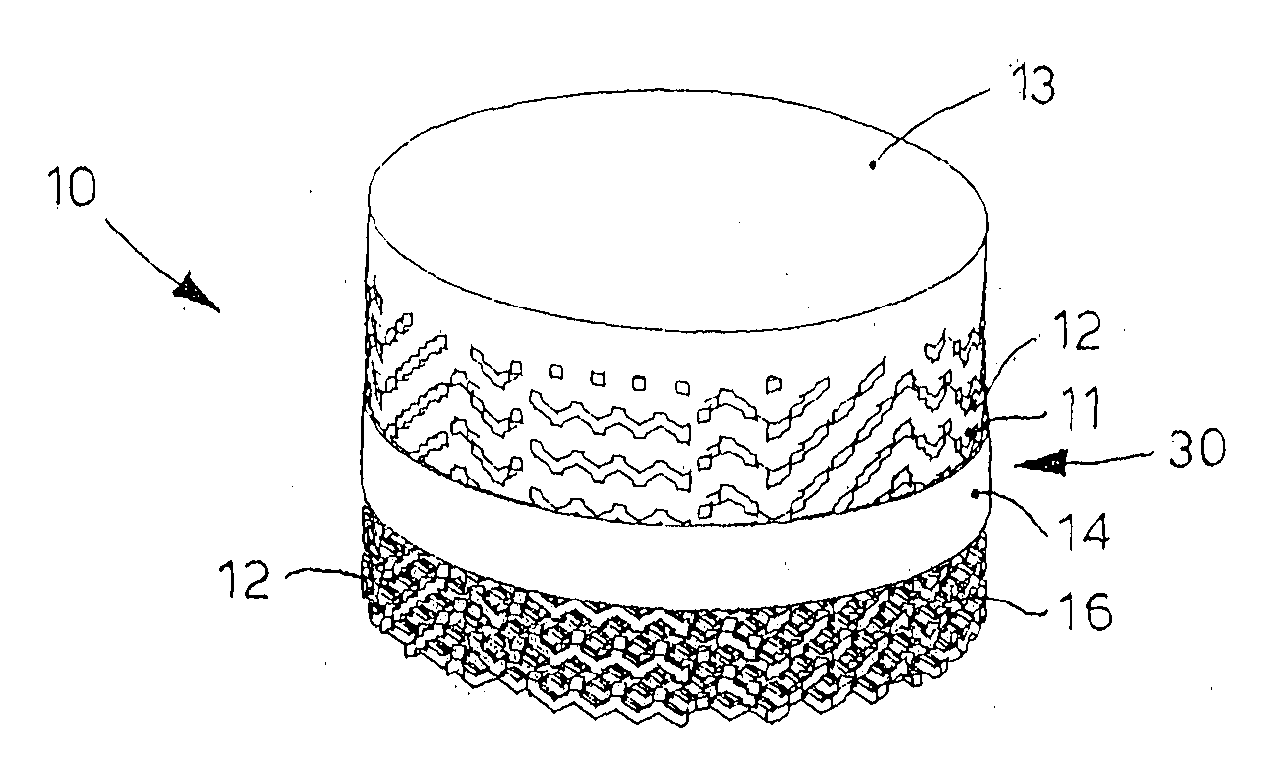
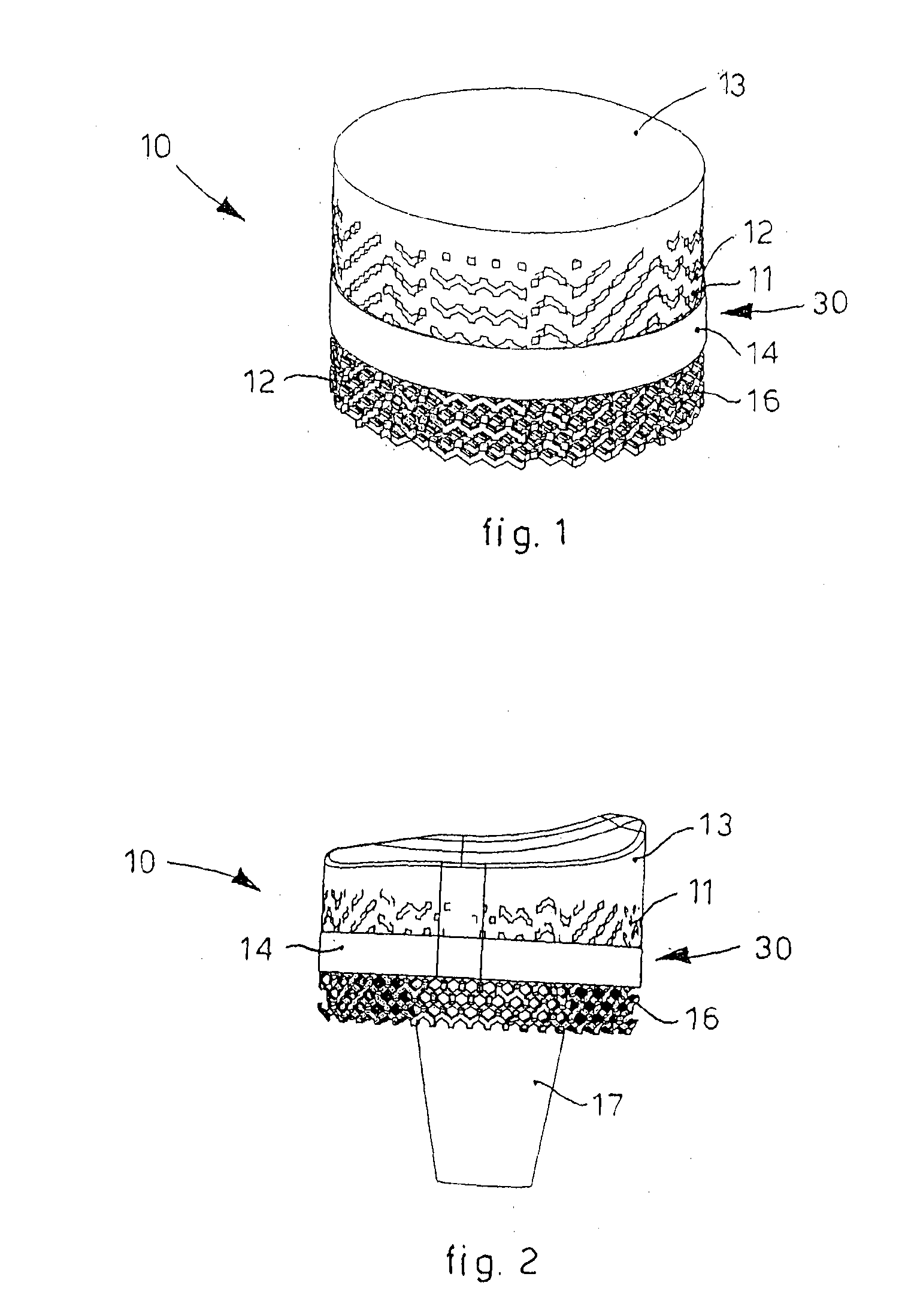
[0045]With reference to FIG. 1 a first simplified form of embodiment of the integrated prosthetic element 10 is shown.

[0046]The integrated prosthetic element 10 in FIG. 1 comprises a metal support 30 and a plastic insert 13 made solid in said metal support 30.

[0047]The metal support 30 comprises a first surface, for example internal, defining a first layer or solidarization layer 11 of the plastic insert 13; in a position directly adjacent to the solidarization layer 11 there is a compact layer 14.

[0048]The solidarization layer 11 has blind holes and / or cavities 12 on the surface which extend internally and are intercommunicating with each other. An example of th...


PUM

PropertyMeasurementUnit
Lengthaaaaaaaaaa
Widthaaaaaaaaaa
Biocompatibilityaaaaaaaaaa

Abstract

Integrated prosthetic element usable for bone implant operations or as a bone filler or replacement, comprising at least a metal support and an insert made of plastic material coupled with at least a first surface of said metal support so as to define a wear surface, or insert, of adjustable thickness. The metal support comprises, on the side opposite said first surface, a second surface intended to be coupled with the bone part on which the prosthesis or bone replacement is installed. The first surface comprises a layer having cavities or holes distributed in a substantially uniform manner and suitable for anchorage and solidarization of the plastic material that makes up the insert, while said second surface comprises a porous layer suitable to optimize the bone anchorage. The first surface and the second surface are separated by a compact layer that stops the plastic material in the step of forming the plastic insert. The cavities or holes of the first surface have bigger shapes and sizes than, and in any case different from, the pores of the second surface.

Description

FIELD OF THE INVENTION[0001]The present invention concerns an integrated prosthetic element for applications in prostheses and bone replacements.[0002]More precisely, the present invention concerns an integrated prosthetic element and the relative method of production, which can be used for the restoration of animal articulations, more specifically, human articulations.[0003]The invention is applied in the medical field of implants of bone prostheses and bone replacements.BACKGROUND OF THE INVENTION[0004]Prostheses are known, which are applied in parts of the human or animal body, normally made essentially by a metal support or shell to which an insert made of plastic material is coupled solidly, which facilitates the sliding of the mobile part of the prosthesis, thus allowing it to move and reducing wear on the parts.[0005]The choice of material for the metal support and the plastic material of the insert is dictated by the use of bio-compatible materials; generally the metal suppo...

Claims


Application Information

Patent Timeline
IPC IPC(8): A61F2/02
CPCA61F2/30A61F2/3094A61F2002/30065A61F2002/30772A61F2002/3092A61F2310/00131A61F2002/30985A61F2210/0071A61F2310/00023A61F2310/00029A61F2002/30971B33Y80/00
Inventor PRESSACCO, MICHELE
Owner LIMA CORPORATE SPA
Learn More