Separator for battery and battery

a separator and battery technology, applied in the field of separators for batteries and batteries, can solve the problems of deformation of separators, shrinkage and generation of holes, insulation breaking, etc., and achieve the effects of low cost, easy handling, and excellent mass-productivity

Inactive Publication Date: 2004-04-20
MITSUBISHI ELECTRIC CORP
View PDF16 Cites 88 Cited by
  • Summary
  • Abstract
  • Description
  • Claims
  • Application Information

AI Technical Summary

Benefits of technology

According to this, there is an effect that highly safe separator capable of efficiently cutting off ion conductivity at a high temperature can be obtained without the risk of its melting which causes break of insulation.
FIG. 2 is a cross sectional view illustrating another embodiment of the present invention. In the figure, numeral 3c indicates a third porous layer comprising a thermoplastic resin as a main component which is constructed from the same material as the first porous layer 3a. The separator 3 in FIG. 2 is formed with the first and third porous layers having a thermoplastic resin as a main component on the both surfaces of the second porous layer 3b. The separator 3 has a function that the second separator 3b connects two of the first porous layers 3a. And since the both surfaces are the first porous layers, there is an effect that the separator can be easily handled.

Problems solved by technology

However, the above separator had a problem that not only the minute holes were closed but also at a temperature higher than a certain degree, the separator itself melted to cause deformation of the separator such as shrink and generation of holes due to melting and insulation was broken.
At this time, since large short-circuit current is generated between the positive electrode and the negative electrode, there has been a problem that the temperature of the battery further increases due to exothermic reaction, leading to further increase of short-circuit current.
However, such a separator had problems that it could not control ion conductivity at a high temperature and that preparation of the battery became complicated.

Method used


Image

  • Separator for battery and battery
  • Separator for battery and battery
  • Separator for battery and battery

Examples


example 2

(Process for Preparing Separator)

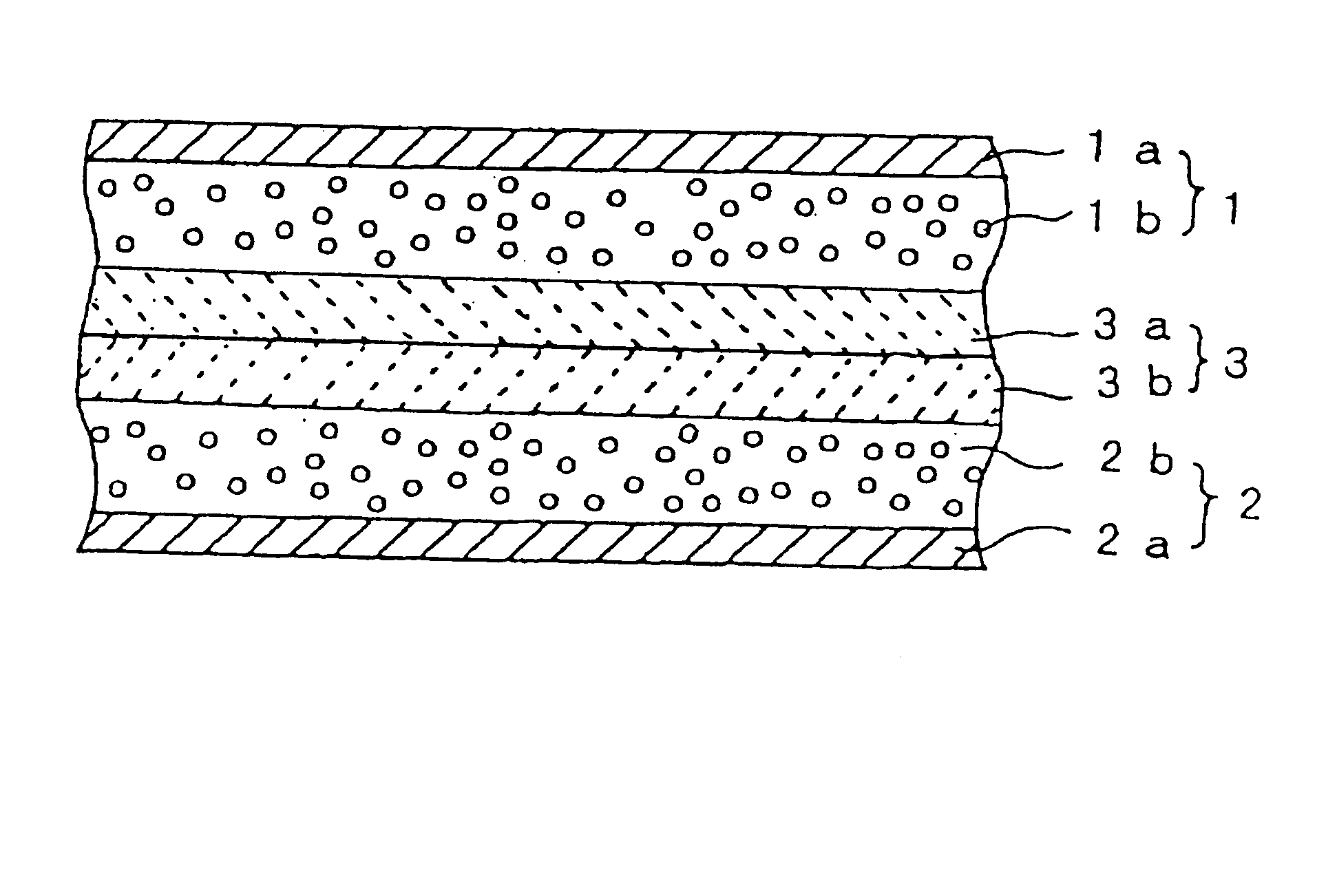
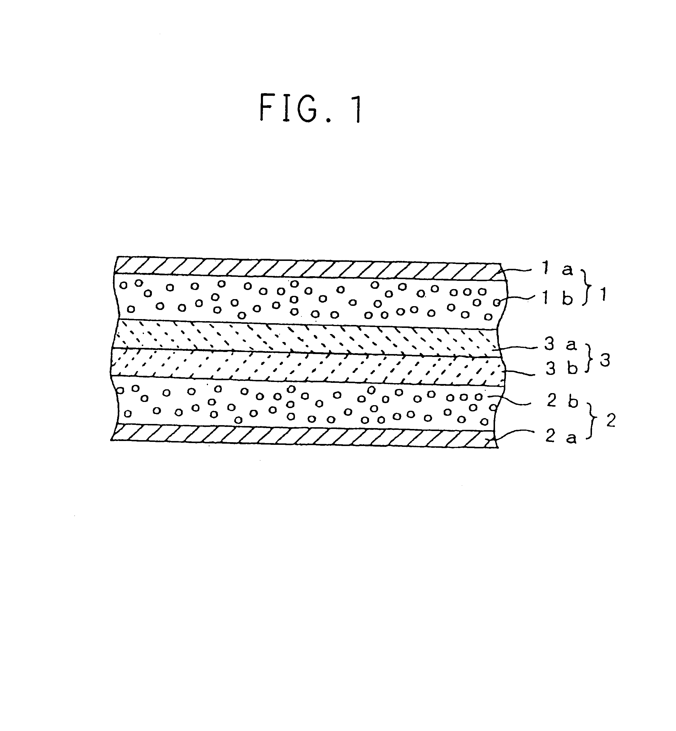
Glass fiber (having a diameter of 5 .mu.m) was measured by using a micrometer to spread it as uniformly as possible to the extent that the thickness becomes at most 20 .mu.m. Thereto was sprayed 10% poly(vinyl alcohol) aqueous solution to mount a porous polypropylene sheet (trade name CELL GUARD #2400 available from Hochst Celanese Co., Ltd.) thereon. After sufficient drying, there was prepared a separator 3 wherein a second porous film 3b comprising the glass fiber is laminated on a first porous layer 3a.

(Evaluation of Battery)

By using this separator, a battery was prepared in the same manner as in Example 1. As to the characteristics of the battery, energy density per weight was 60 Wh / kg.

Also, in case of heating the battery in charging condition to 150.degree. C., there were found no unusual conditions such as short-circuit of the electrodes due to melting of the separator 3.

example 3

(Process for Preparing Separator)

Alumina ultra-fine particles (available from Degussa Co., Ltd.) and 30% by weight of poly(vinylidene fluoride) were stirred by using a colloid mill to prepare a mixture containing about 15% by weight thereof based on N-methylpyrolidone. It was applied to a porous polypropylene sheet (trade name CELL GUARD #2400 available from Hochst Celanese Co., Ltd.) according to screen-printing and was dried to prepare a separator 3 wherein a second porous film 3b comprising the alumina ultra-fine particles was laminated on a first porous layer 3a.

(Evaluation of Battery)

By using this separator, a battery was prepared in the same manner as in Example 1. As to the characteristics of the battery, energy density per weight was 70 Wh / kg.

Also, in case of heating the battery in charging condition to 170.degree. C., there were found no unusual conditions such as short-circuit of the electrodes due to fusion of the separator 3.

example 4

(Process for Preparing Separator)

Cross-linked acrylic ultra-fine particles (MP300F available from Soken Chemicals Co., Ltd.) and 30% by weight of poly(vinylidene fluoride) were stirred by using a colloid mill to prepare a mixture containing about 10% by weight thereof based on N-methylpyrolidone. It was applied to a porous polypropylene sheet (trade name CELL GUARD #2400 available from Hochst Celanese Co., Ltd.) according to screen-printing and was dried to prepare a separator 3 wherein a second porous film 3b comprising the cross-linked acrylic ultra-particles was laminated on a first porous layer 3a.

(Evaluation of Battery)

By using this separator, a battery was prepared in the same manner as in Example 1. As to the characteristics of the battery, energy density per weight was 75 Wh / kg.

Also, in case of heating the battery in charging condition to 150.degree. C., there were found no unusual conditions such as short-circuit of the electrodes due to fusion of the separator 3.


PUM

PropertyMeasurementUnit
particle sizeaaaaaaaaaa
softening temperatureaaaaaaaaaa
particle sizeaaaaaaaaaa

Abstract

Conventional separators had a function that their melting made minute holes inside the separator smaller, leading to cut off of ion conductivity in temperature increase due to unusual conditions such as short circuit. However, there was a problem that, at a temperature higher than a certain degree, not only the minute holes were closed but also the separator itself was melted to cause deformation of the separator such as shrink and generation of holes due to melting and insulation was broken. The present invention has been carried out in order to solve the above problems. The separator for batteries of the present invention comprises a first porous layer (3a) containing a thermoplastic resin as a main component and a second porous layer (3b) laminated on the first porous layer (3a), which has higher heat resistance than that of the first porous layer (3a).

Description

The present invention relates to a separator for a battery. More particularly, the present invention relates to a separator for a battery having high safety, a battery using the same and to a process for preparing the separator.There is a growing demand for downsizing and lightening of portable electric appliances and the achievement greatly depends upon improvement of battery performance. There have been various development and improvement of batteries in order to meet the demand. Performance required to a battery includes high voltage, high energy density, safety, variety of shape and the like. A lithium ion battery is a non-aqueous electrolytic solution battery, which is expected to achieve high voltage and high energy density, and active improvement is going on even at present. Also, there has been carried out research for lithium metal batteries which is expected to have further higher energy density.These non-aqueous batteries comprise a positive electrode, a negative electrod...

Claims


Application Information

Patent Timeline
Patent Type & Authority Patents(United States)
IPC IPC(8): H01M2/16H01M2/14H01M6/00H01M6/50H01M8/02H01M50/403H01M50/443H01M50/451
CPCH01M2/145H01M2/16H01M2/1686H01M8/0202H01M2200/10Y02E60/50Y02E60/10H01M50/403H01M50/451H01M50/443H01M50/414H01M50/449H01M50/489Y02P70/50
Inventor YOSHIDA, YASUHIROHIROI, OSAMUHAMANO, KOUJITAKEMURA, DAIGOAIHARA, SIGERUSHIOTA, HISASHIARAGANE, JUNURUSHIBATA, HIROAKIMURAI, MICHIOINUZUKA, TAKAYUKI
Owner MITSUBISHI ELECTRIC CORP
Why Eureka
Try Eureka