

Mechanical locking of floor panels with a glued tongue
a technology of floor panels and tongues, applied in the field of tongues, can solve the problems of difficult glueing of plastic to wood, tongues may fall out of the groove, etc., and achieve the effect of facilitating the bending of the protruding groov
- Summary
- Abstract
- Description
- Claims
- Application Information
AI Technical Summary
Benefits of technology
Problems solved by technology
Method used
Image

Examples
first embodiment
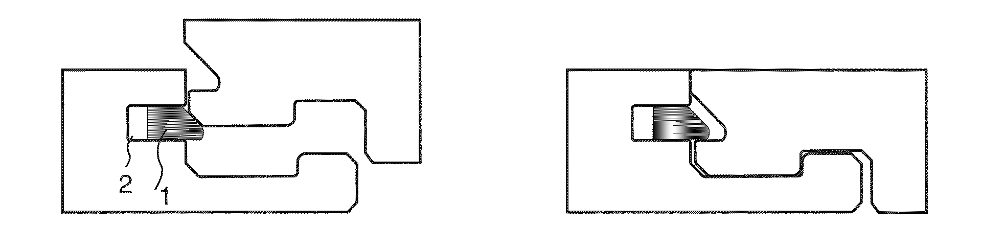
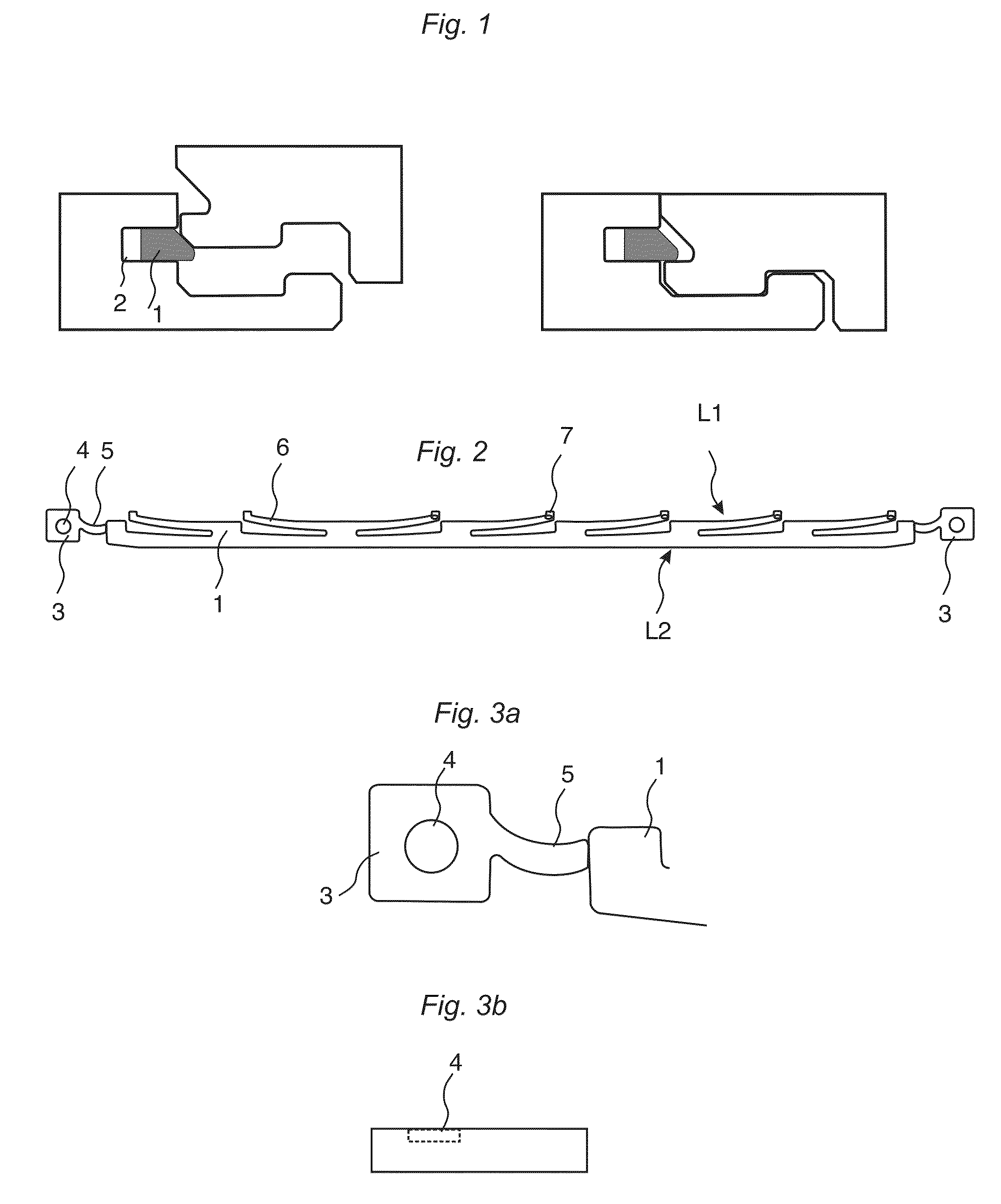
[0037]FIG. 2 shows a flexible tongue 1, made of moulded plastic material, which comprises two edge sections 3, which are intended to be used to glue the tongue into a groove 2.
[0038]The tongue is of an elongated shape and comprising in this preferred embodiment at least two protrusions 6 at a first long edge L1.
[0039]The protrusions are bendable in a plane parallel to the upper surface of the tongue and extending essentially in the parallel plane.
[0040]The tongue has a second long edge L2, which is essentially straight over substantially the whole length of the tongue.
[0041]The edge section 3 comprises a glue pocket 4 where glue is applied, preferably by an inserting equipment, which also positions the tongue into a groove of a panel. Friction connections 7 may be used to hold the tongue in the groove until the glue cures.
[0042]FIG. 3a shows the edge section from above. FIG. 3b shows a cross section of the edge section. A glue pocket 4 is preferably formed as a local cavity.
[0043]Th...
second embodiment
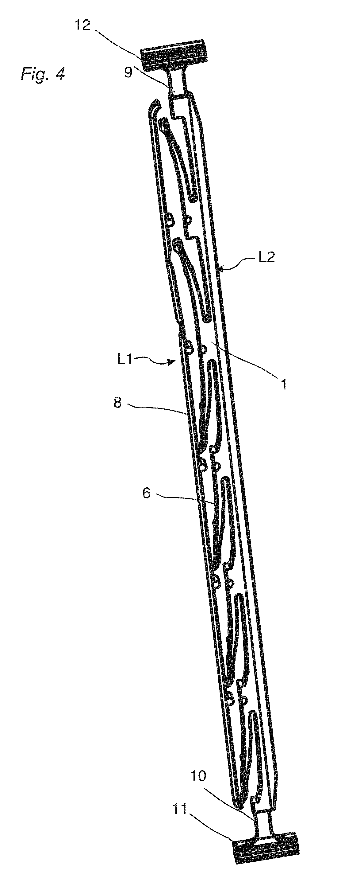
[0044]FIG. 4 shows a flexible tongue 1, made of moulded plastic material, which is provided with a gluing strip 8 configured to be used to glue the tongue into a groove 2. Parts 11, 12 formed by moulding inlets from a moulding tool are shown at the first 9 and the second edge 10 of the tongue 1. These parts are used to facilitate the insertion of the tongue into a groove 2 of a building panel, preferably a floor panel.
[0045]The tongue is of an elongated shape and comprising in the second embodiment at least two protrusions 6 at a first long edge L1.
[0046]The protrusions are bendable in a plane parallel to the upper surface of the tongue and extending essentially in the parallel plane.
[0047]The tongue has a second long edge L2, which is essentially straight over substantially the whole length of the tongue.
[0048]FIG. 5 shows the first edge 9 of second embodiment of the tongue. The outer ends 17 of the protrusions 6 at the first edge are free from the gluing strip 8 to facilitate a mo...
third embodiment
[0055]FIG. 8 shows the first edge 9 of the tongue.
[0056]FIG. 9 shows the second edge 10 of the third embodiment of the tongue 1.
[0057]The third embodiment of the tongue is provided with said edge sections 3 on each edge of the tongue. Said edge section is provided with a protruding friction connection, configured to hold the tongue in the correct position until the glue is cured. A flexible link 5 connects the edge section 3 to the main tongue body.
[0058]The edge sections are each provided with an outer protruding stop part 22, which overlap an inner stop part 21, which protrudes from each edge 9, 10 of the tongue, wherein said inner and outer stop part cooperates to limit the displacement of the tongue 1 in the groove 2.
[0059]The edge sections are further provided with a breaking part 20, configured to be broken when the tongue 1 is inserted into the groove 2.
[0060]Glue may be used that glues to a wood based material and cures such that a part of the glue will form a small protrusi...
PUM
 Abstract
Description
Claims
Application Information