Sound Attenuation Stud

Active Publication Date: 2013-01-10
ETEX AUSTRALIA PTY LTD
View PDF9 Cites 2 Cited by
  • Summary
  • Abstract
  • Description
  • Claims
  • Application Information

AI Technical Summary

Benefits of technology

[0007]For a given stud thickness, the lengths of the first, second and third portions may be small enough to resist substantial deformation in use to there

Problems solved by technology

In buildings such as high rise apartment blocks, sound (esp. noise) undesirably carries b

Method used


Image

  • Sound Attenuation Stud
  • Sound Attenuation Stud
  • Sound Attenuation Stud

Examples


Example

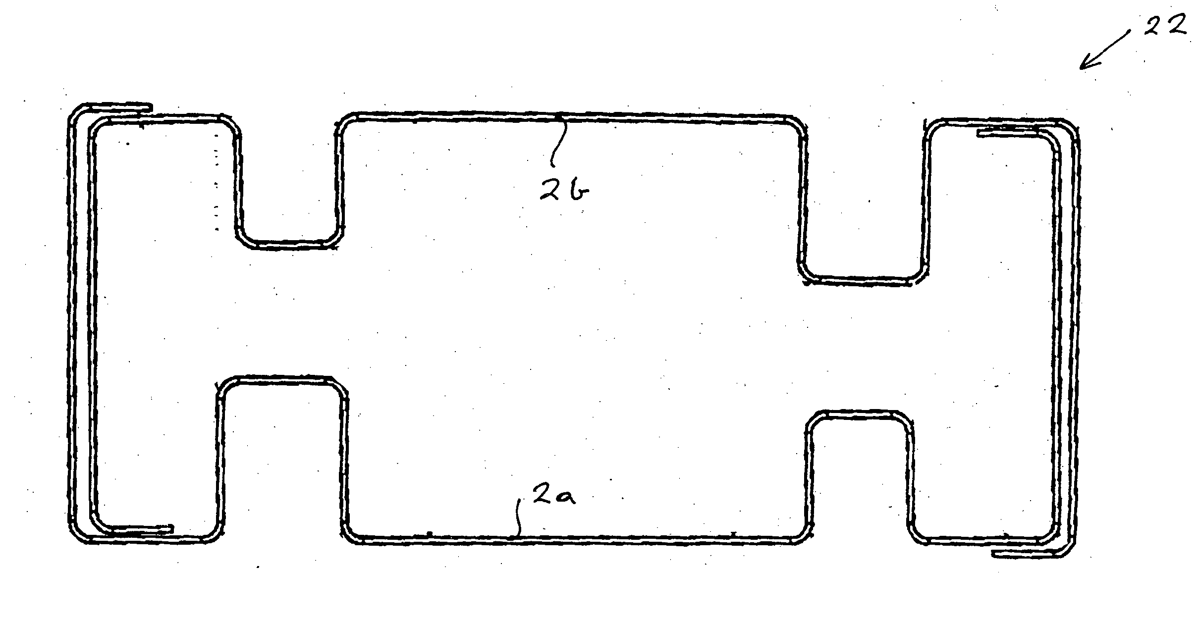
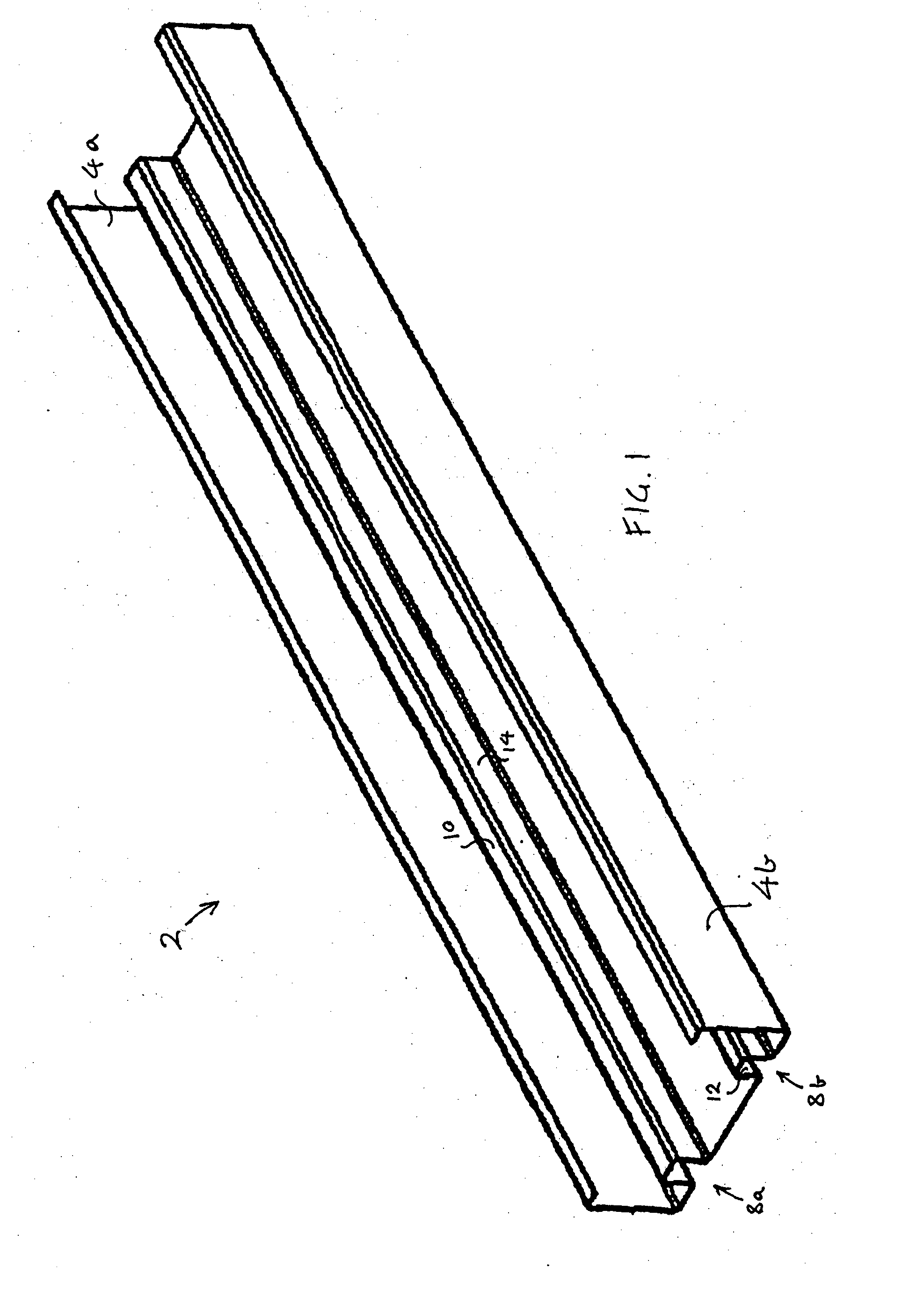
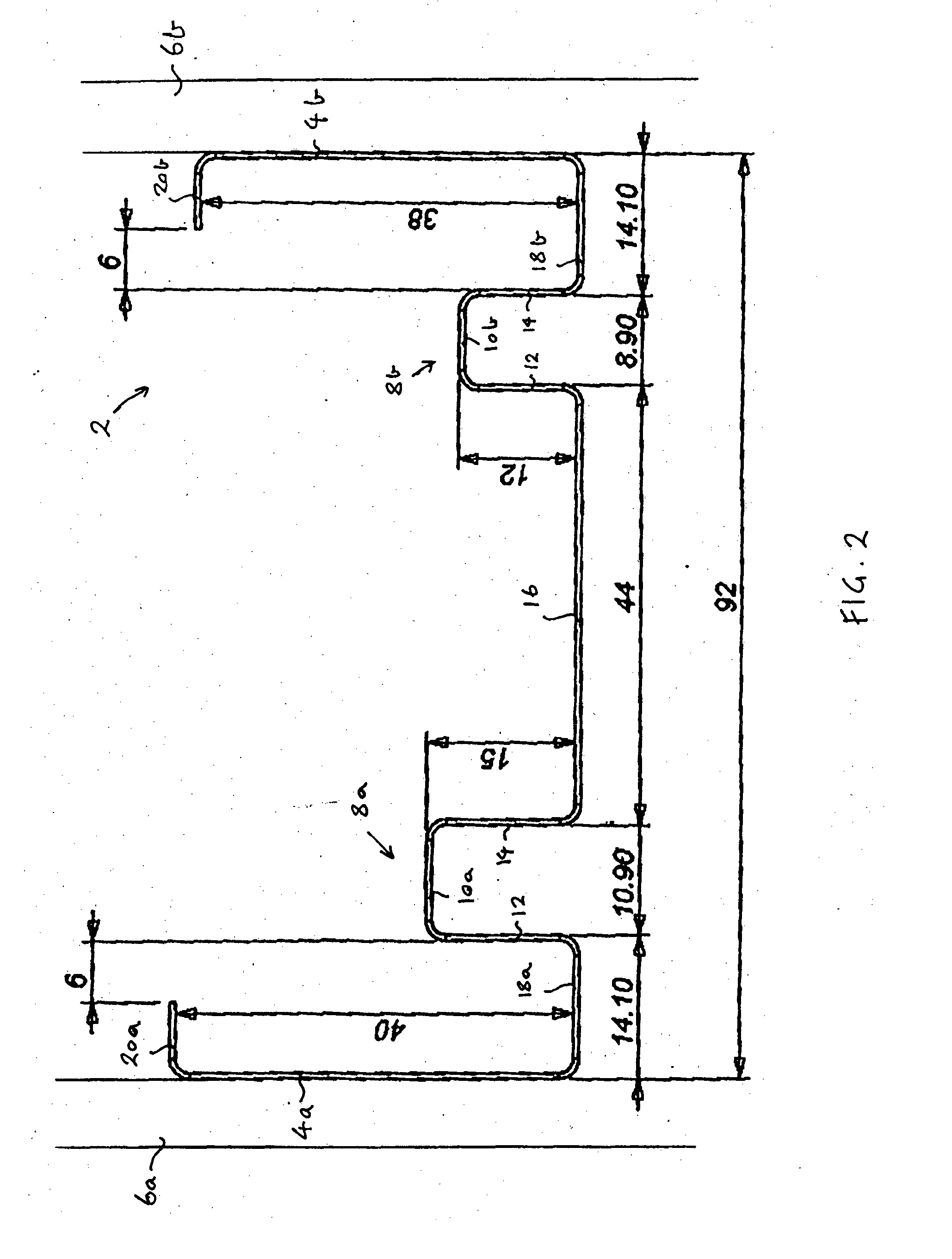
[0018]According to an embodiment of the present invention, there is provided an extruded metal (e.g. steel or aluminium) sound attenuation stud 2 as shown in FIGS. 1 and 2. As can best be seen in FIG. 2, the stud 2 includes two engagement portions 4a, 4b for engaging within a hollow building wall having two (or more) sheets of plasterboard 6a, 6b. The stud 2 includes exactly two sound attenuation formations 8a, 8b located between the engagement portions 4a, 4b. Each sound attenuation formation 8 includes a first portion 10 relative to which a second portion 12 and a third portion 14 orthogonally extend. The stud 2 is of uniform thickness, and the lengths of the first, second and third portions 10, 12, 14 are small enough to resist substantial deformation in use to thereby provide a structurally stable sound attenuation stud 2. A detailed description of the stud 2 is provided below.

[0019]With particular reference to FIG. 2, the second and third portions 12, 14 of a first sound attenu...


PUM


Abstract

The present invention relates to a sound attenuation stud. The stud includes two engagement portions for engaging within a building element. The stud also includes two sound attenuation formations located between the engagement portions. Each sound attenuation formation includes a first portion relative to which second and third portions extend. Preferably, each portion is either parallel or orthogonal with all the other portions.

Description

TECHNICAL FIELD[0001]The present invention relates to a sound attenuation stud.BACKGROUND[0002]The reference to any prior art in this specification is not, and should not be taken as an acknowledgement or any form of suggestion that the prior art forms part of the common general knowledge.[0003]In buildings such as high rise apartment blocks, sound (esp. noise) undesirably carries between building elements such as hollow walls, ceilings or floors that can separate rooms.[0004]AU 2004203463 discloses a sound attenuation stud for engaging within a building element. The stud includes a sound attenuation formation which substantially deforms in use to provide sound attenuation.[0005]The preferred embodiment of the present invention provides a more structurally stable sound attenuation stud.SUMMARY OF THE INVENTION[0006]According to one aspect of the present invention, there is provided a sound attenuation stud including two engagement portions for engaging within a building element and ...

Claims


Application Information

Patent Timeline
IPC IPC(8): E04B1/82
CPCE04B2/7412E04B2/789E04C3/07E04C2003/0417E04C2003/0473E04C2003/0434E04C2003/0439E04C2003/0456E04C2003/0421
Inventor BEAN, STEPHEN CHARLES
Owner ETEX AUSTRALIA PTY LTD
Why Eureka
Try Eureka