
Cylindrical vessel made of carbon and process for making silicon

a cylindrical vessel and carbon technology, applied in the direction of silicon compounds, manufacturing tools, chemistry apparatus and processes, etc., can solve the problems of reducing production efficiency, cracking of carbon materials, and requiring very troublesome procedures, so as to reduce the formation of sic, the effect of resisting deformation and significant suppressing of vessel cracking or other adverse phenomena

Inactive Publication Date: 2012-10-09
TOKUYAMA CORP
View PDF11 Cites 0 Cited by
  • Summary
  • Abstract
  • Description
  • Claims
  • Application Information

AI Technical Summary

Benefits of technology

The carbon vessel significantly reduces permeation and SiC formation, preventing vessel cracking and extending its service life, while minimizing carbon and impurity incorporation into the silicon product, resulting in higher purity and more efficient polycrystalline silicon production.

Problems solved by technology

However, the Siemens process has a problem in that it is required to carry out very troublesome procedures such as installation of a silicon rod used as a seed, electrical heating, deposition, cooling, taking-out, and cleaning of a bell jar since the deposition is performed in a batch mode.
Such permeation with silicon melt and formation of SiC cause a stress to the inside of the carbon material due to volumetric expansion associated with formation of SiC, and thereby the carbon material is cracked.
Thus, there has been a problem of reducing production efficiency.
However, in such a method of applying SiC-coating on the surface of the reaction vessel, the effect of preventing permeation with silicon melt is not sufficient and still cracking of the reaction vessel and the like occur resulting in stopping operation.
Thus, the production efficiency has not been sufficiently improved yet.

Method used


Image

  • Cylindrical vessel made of carbon and process for making silicon
  • Cylindrical vessel made of carbon and process for making silicon

Examples


example 1

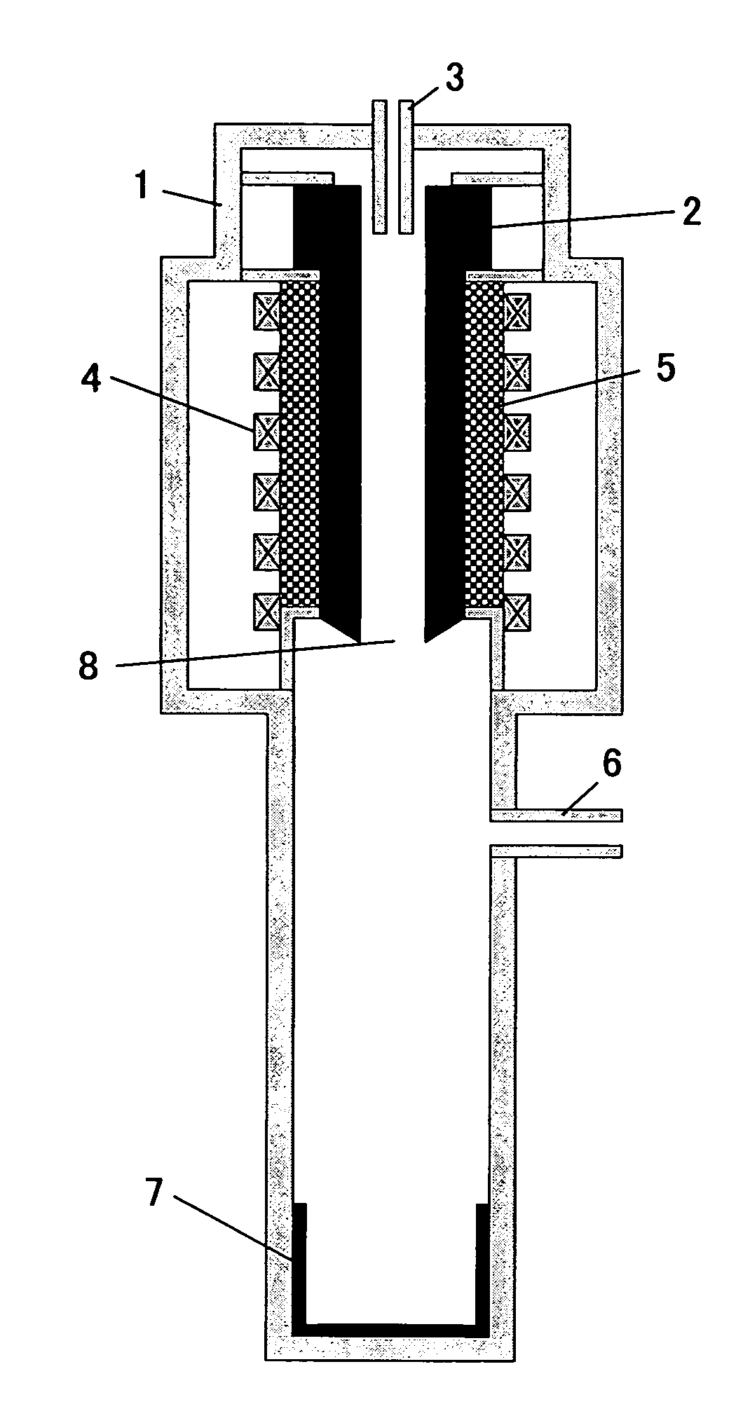
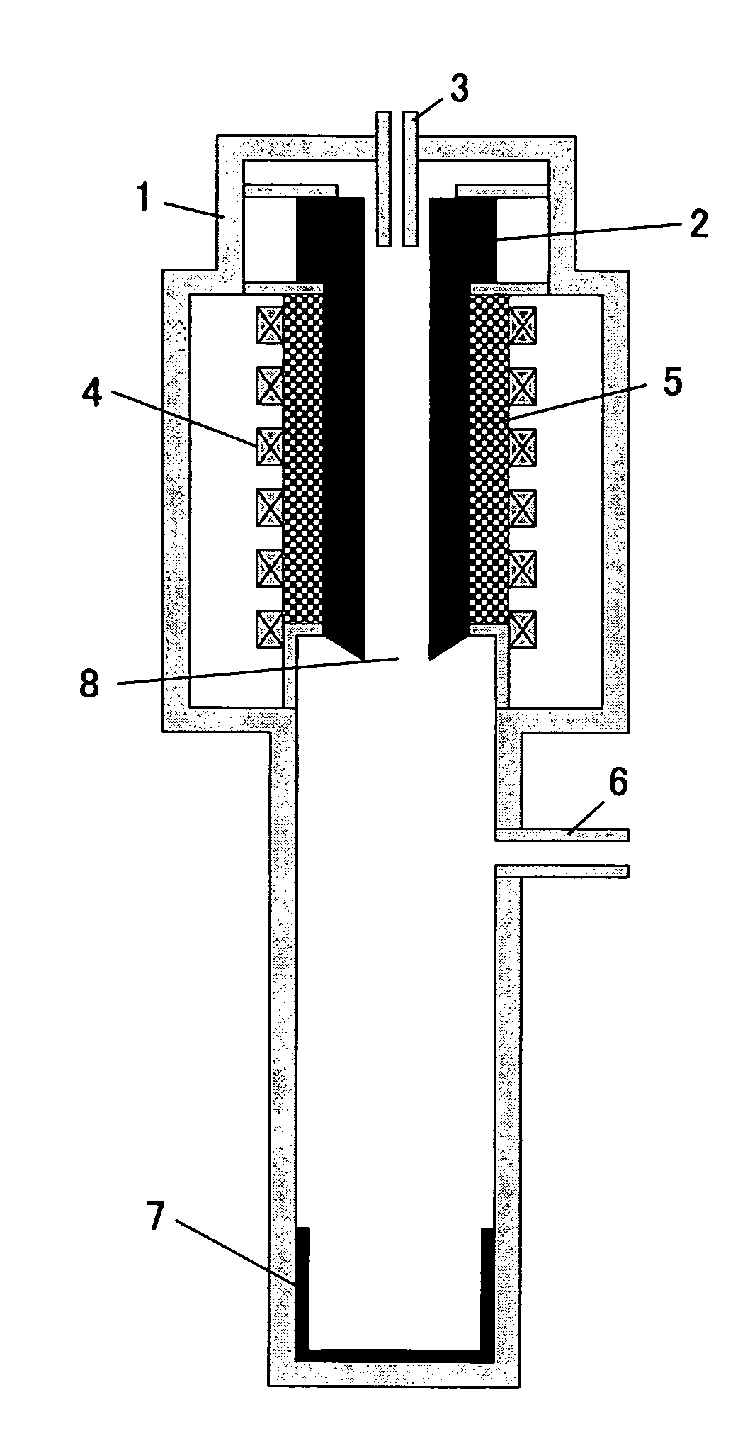
[0040]On a reaction apparatus as shown in FIG. 1 was mounted a reaction vessel for generation of silicon (inside diameter: 45 mm, wall thickness: 15 mm, entire length: 1000 mm) made of a carbon material (thermal expansion coefficient: 4.8×10⁻⁶ / ° C.) having a bulk specific gravity of 1.82. A mixed gas containing 10 kg / H of trichlorosilane and 40 Nm3 / H of hydrogen was passed into the reaction vessel, and the reaction vessel was heated to a temperature of 1450° C. or higher by high-frequency heating to deposit polycrystalline silicon for 100 hr. After completion of the reaction, the reaction vessel was removed from the reaction apparatus and the state of the reaction vessel (the presence of cracking of the reaction vessel and the depth of the inside of the reaction vessel permeated with silicon) was observed. The results are shown in Table 1.

[0041]Silicon deposition reaction was performed in the same manner as described above except for use of a reaction vessel for generation of silico...

examples 2 to 4

[0042]Silicon deposition reaction was performed in the same manner as Example 1 except for use of a reaction vessel for generation of silicon made of a carbon material having the bulk specific density and the thermal expansion coefficient shown in Table 1, and the state of the reaction vessel after completion of the reaction was observed. The results are shown in Table 1.


PUM

PropertyMeasurementUnit
specific gravityaaaaaaaaaa
thicknessaaaaaaaaaa
specific gravityaaaaaaaaaa

Abstract

A cylindrical vessel made of carbon is used in the production of silicon. The inner surface of the vessel comes into contact with a silicon melt, wherein the permeation with silicon melt is reduced, formation of SiC is suppressed, and the vessel is resistant to deformation even when volumetric expansion ascribable to silicon is brought about. The carbon-made cylindrical vessel is made of a carbon material having a bulk specific gravity of 1.8 or more. The thermal expansion coefficient of the carbon material at 350 to 450° C. is preferably 3.5×10⁻⁶ / ° C. to 6.0×10⁻⁶ / ° C. A process for producing silicon uses said vessel wherein a chlorosilane is reacted with hydrogen.

Description

TECHNICAL FIELD[0001]The present invention relates to a cylindrical vessel made of carbon and a production process of silicon using said vessel. More particularly, the present invention relates to a cylindrical vessel made of carbon that is suitably used in generating silicon by reaction of a chlorosilane with hydrogen and made of a carbon material that can resist contact with molten silicon, and a production process of silicon using said vessel.BACKGROUND ART[0002]Polycrystalline silicon is used as a raw material for semiconductors, solar cells and the like, which are presently utilized in various fields and expected to be further developed and demanded in future, and therefore high-purity polycrystalline silicon is desired to be produced effectively. As a conventional production process of polycrystalline silicon, there has been, for example, the Siemens process in which a surface of a silicon rod placed inside a bell jar is heated and brought into contact with a source gas for si...

Claims


Application Information

Patent Timeline
Patent Type & Authority Patents(United States)
IPC IPC(8): C01B33/00C01B33/02B22D41/05C21B3/00C01B33/029C01B33/03C04B35/52C04B35/565
CPCC01B33/03C04B35/565C04B2235/77C04B2235/9607
Inventor NAKASHIMA, JUNICHIROUWAKAMATSU, SATORUSAKITA, MANABU
Owner TOKUYAMA CORP
Learn More