Display apparatus

a technology of display apparatus and display screen, which is applied in the direction of printers, tactile signalling systems, camera focusing arrangement, etc., can solve the problems of limited conventional stereoscopic display and bodily discomfort of the viewer

Active Publication Date: 2013-01-10
IND TECH RES INST
View PDF1 Cites 25 Cited by
  • Summary
  • Abstract
  • Description
  • Claims
  • Application Information

AI Technical Summary

Problems solved by technology

Conventional stereoscopic displays are limited by the software and hardware restrictions of the planar display or projection techniques adopted, in which a user is required to wear a special pair of stereoscopic glasses when viewing the stereoscopic images.
Even with auto-stereoscopic techniques, a severe crosstalk issue exists which causes bodily discomfort for the viewer when viewing the stereoscopic images with crosstalk.
However, this operating mode is conducive to germ contamination since the touch control interfaces have been touched for extended periods of time.

Method used


Image

  • Display apparatus
  • Display apparatus
  • Display apparatus

Examples


Embodiment Construction

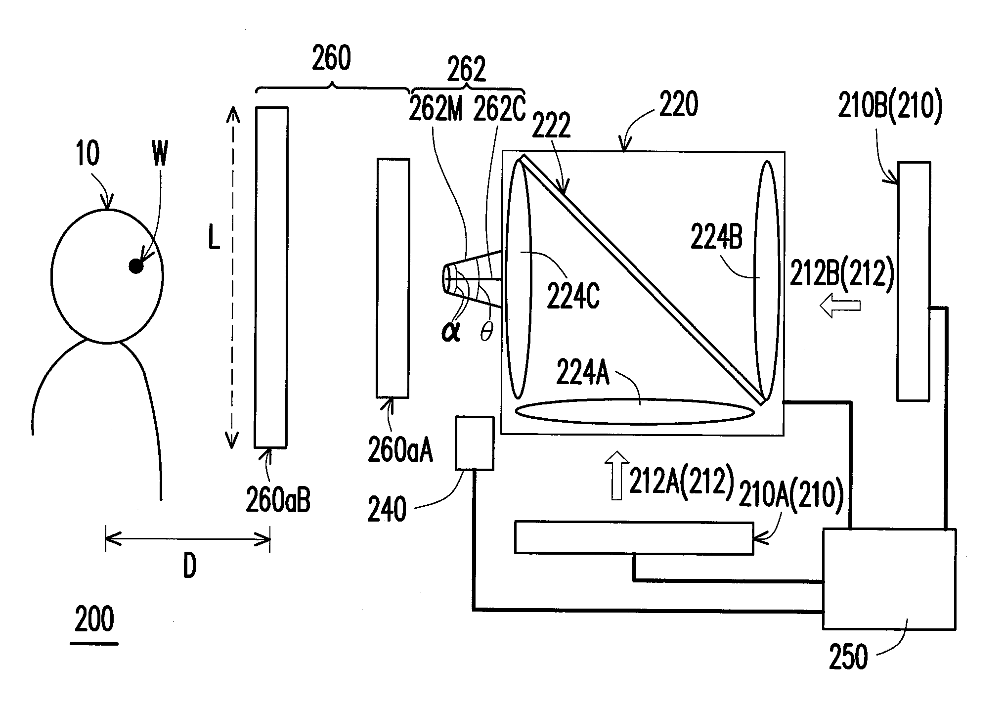
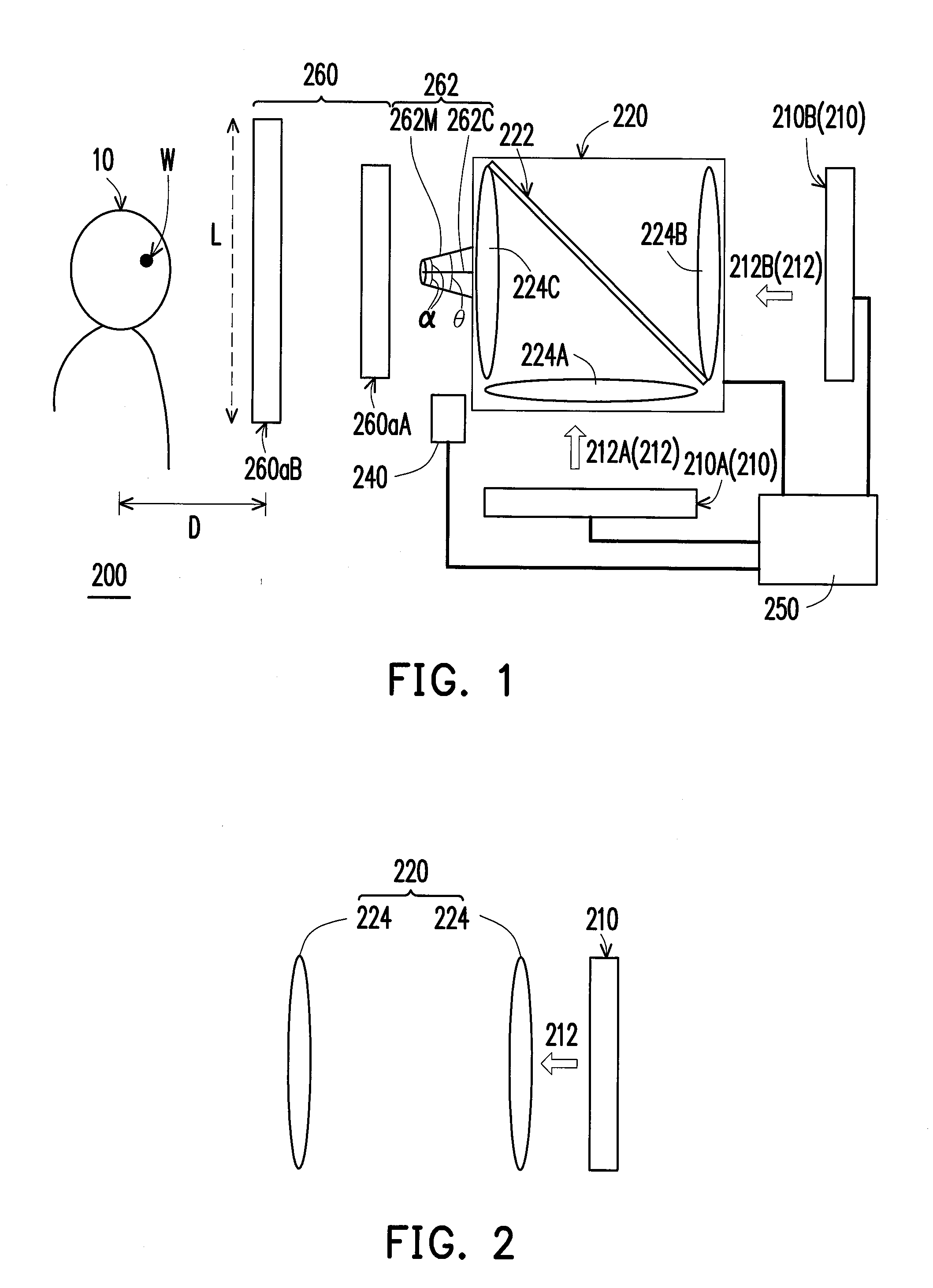
[0025]FIG. 1 is a schematic view illustrating a display apparatus according to an embodiment of the disclosure. Referring to FIG. 1, a display apparatus 200 is suitable for viewing by a user 10. The display apparatus 200 includes at least an image generator 210, a projection lens set 220, a depth detecting module 240, and a control unit 250. The image generator 210 displays at least an image 212, for example a first image generator 210A displays an first image 212A, and a second image generator 210B displays an second image 212B. The image generator 210 is, for example, a display panel, a light emitting device, or an object being illuminated by light. The projection lens set 220 is located between the image generator 210 and the user 10. The image 212 projected by the projection lens set 220 generates a floating real image 260 between the projection lens set 220 and the user 10.

[0026]Moreover, the control unit 250 is electrically connected to the image generator 210, the projection ...


PUM


Abstract

A display apparatus including an image generator, a projection lens set, a depth detecting module detecting the position of user, and a control unit is provided, wherein the control unit is electrically connected to the image generator, the projection lens set and the depth detecting module. An image displayed by the image generator is projected through the projection lens set and generates a floating real image between the projection lens set and the user. Each beam forming the floating real image has a light-cone angle θ. The image generator and the projection lens adjust the position of the floating real image according to the position of user. The size of the floating real image is L, the distance between two eyes of the user is W, the distance between the user and the floating real image is D, and the light-cone angle θ satisfies the formula ofθ≥tan-1(L+WD)

Description

CROSS-REFERENCE TO RELATED APPLICATION[0001]This application claims the priority benefits of U.S. provisional application Ser. No. 61 / 506,155, filed on Jul. 10, 2011. In addition, this application claims the priority benefit of Taiwan application serial no. 100149642, filed on Dec. 29, 2012. The entirety of each of the above-mentioned patent applications is hereby incorporated by reference herein and made a part of this specification.BACKGROUND[0002]1. Technical Field[0003]The technical field relates to a display apparatus, and more particularly to a display apparatus having a floating real image.[0004]2. Related Art[0005]In recent years, the continuous advancement of display technologies have resulted in the increasing demands on display quality of displays, such as image resolution, color saturation, and so on. Besides the trend towards high image resolution and color saturation, displays capable of displaying stereoscopic images have been developed to satisfy the user's desire fo...

Claims


Application Information

Patent Timeline
Patent Type & Authority Applications(United States)
IPC IPC(8): G02B27/22G08B6/00G02B27/26G03B21/14G03B21/28G02B30/25
CPCG02B27/2292G02B27/0093G03B35/16H04N13/0475H04N13/04H04N13/0443G03B35/26G02B30/56H04N13/30H04N13/346H04N13/373
Inventor CHAN, YI-JENTIAO, GOLDENCHEN, CHANG-YINGWANG, CHY-LINTSENG, KUN-LUNGLIN, SHANG-YI
Owner IND TECH RES INST
Why Eureka
Try Eureka