Surveillance system and method

a surveillance system and surveillance method technology, applied in the field of surveillance systems, can solve the problems of inability to thoroughly review the security threats of certain cameras, ineffective and practicable human operators, and inability to fully review the security threats of existing systems, so as to reduce the risk of human error, reduce the risk of security threats captured, and reduce the cost of operation.

Inactive Publication Date: 2013-01-10
GLOBAL ADVANCED VISION
View PDF5 Cites 12 Cited by
  • Summary
  • Abstract
  • Description
  • Claims
  • Application Information

AI Technical Summary

Benefits of technology

[0035]Advantageously, the present invention may assist in alleviating the need for human operators to manually review multiple camera feeds in order to identify potential security threats occurring in multiple surveillance zones. Accordingly, the risk of human error occurring when monitoring potential security threats may also be alleviated. Moreover, as the present invention is adapted for implementation using a computerised system, this may also alleviate costs incurred by manual review by human operators, and / or, the cost of purchasing additional display monitors (and storage space) typically required for review by human operators.
[0036]Also advantageously, the present invention may assist in providing a surveillance of all surveillance zones instead of merely focusing attention upon only a selection of surveillance zones assumed to be of “high risk”. Accordingly, this may also alleviate the risk of security threats captured by certain cameras being overlooked.
[0037]The present invention provides yet a further advantage in that by allowing monitoring of all surveillance zones in real-time, this may alleviate the time and costs associated with archiving data captured by certain “low priority” cameras for later review. Nevertheless, where archiving is still desired, captured input datas relating to surveillance zones may be archived by associating specific time stamped portions of the captured input datas with corresponding priority rating values and / or surveillance ranking values calculated with reference to the specific time stamped portions of the captured input datas in seeking to provide ease of searching and / or retrieval of the most pertinent input data.

Problems solved by technology

Unfortunately existing systems such as described above tend to exhibit several problems.
Firstly, it is often impracticable and ineffective for a human operator to thoroughly review each of the multiple camera feeds simultaneously in real-time and potential security threats captured by certain cameras may be missed due to human error.
Whilst additional manpower may be employed to assist in reviewing the multiple camera feeds, this incurs additional labour costs.
Furthermore, as the number of locations being simultaneously monitored increases, the cost of purchasing additional surveillance equipment and the space to house additional display monitors becomes a burden.
However, this approach is still problematic in that the determination of “high priority” and “low priority” camera feeds is merely based on assumptions as to which cameras are more likely to capture a security threat rather than an actual identification of potential security threats captured by multiple cameras in real-time.
Accordingly, there is a risk that actual security threats captured by “low priority” cameras may be overlooked due to the lack of attention paid to such cameras.
Moreover, even with a more select and manageable number of “high priority” camera feeds being reviewed by a human operator, security threats captured by “high priority” cameras may still be missed due to human error.

Method used


Image

  • Surveillance system and method
  • Surveillance system and method
  • Surveillance system and method

Examples


Embodiment Construction

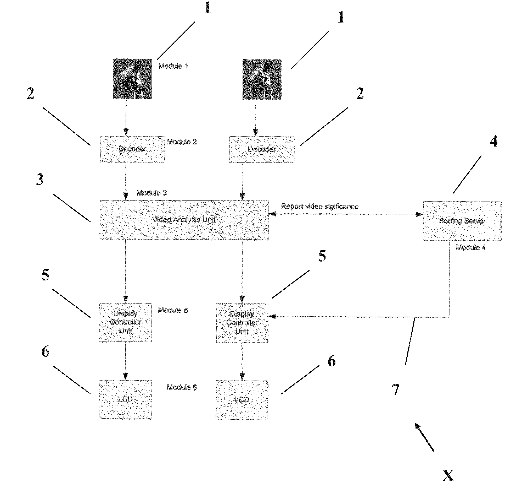
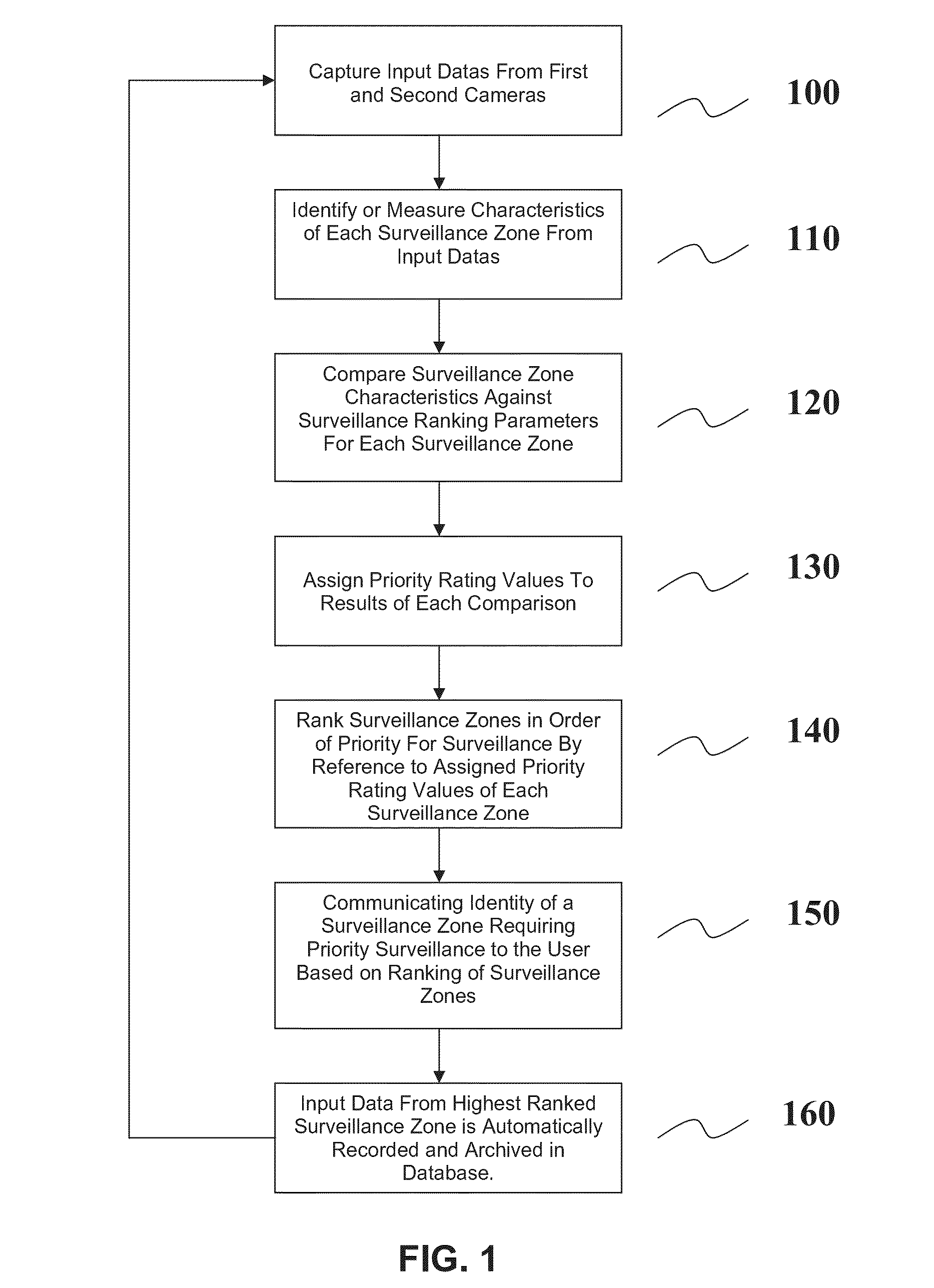
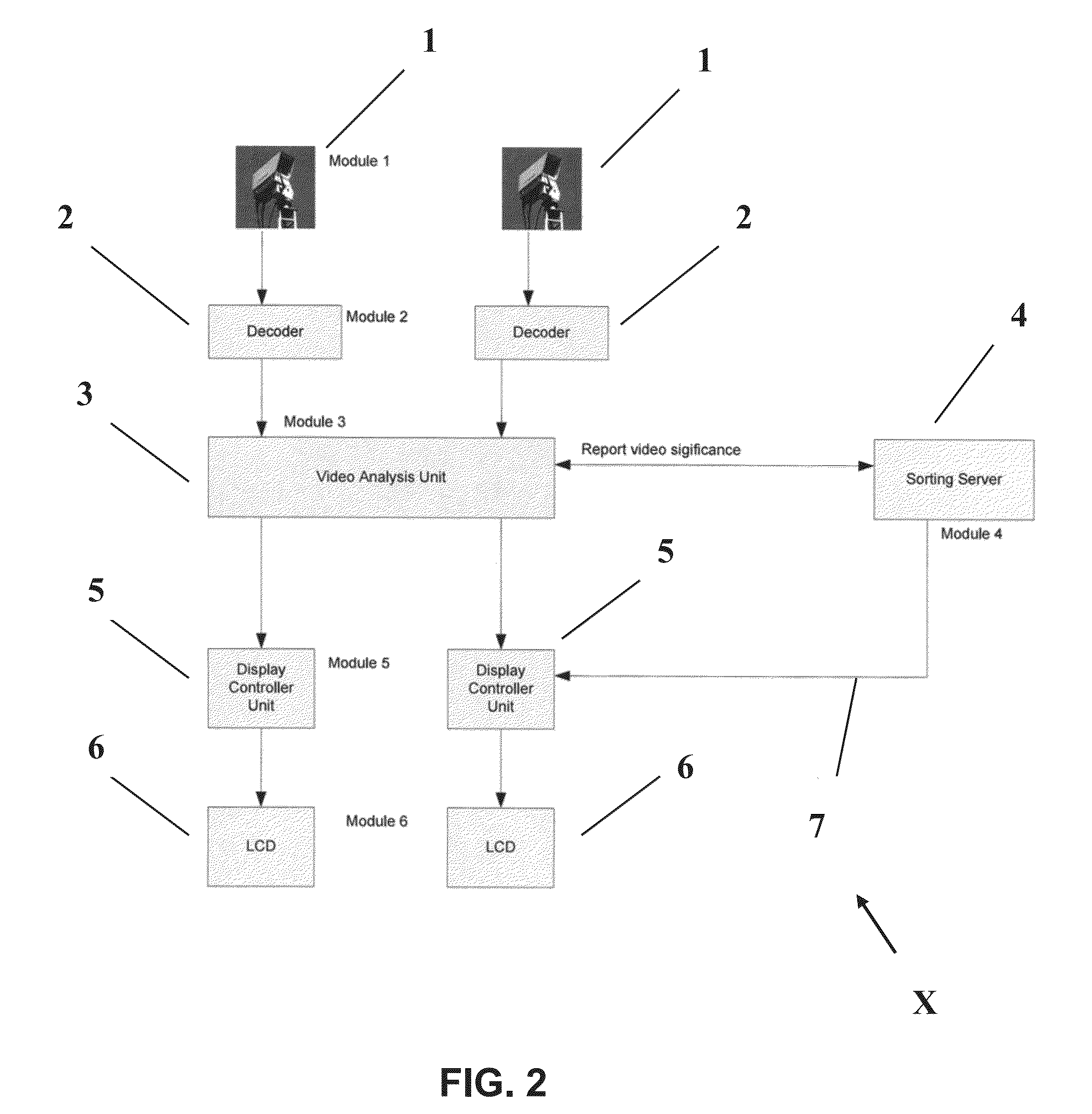
[0041]Preferred embodiments of the present invention will now be described herein with reference to FIGS. 1 and 2. FIG. 1 shows a flowchart of method steps in accordance with a first embodiment of the present invention whilst FIG. 2 shows a block diagram of a computerised system (X) consisting of six functional modules for performing the first embodiment method. Each of the functional modules includes a computer processor, memory store and input and output ports via which data is received or transmitted. The six functional modules are communicably connected via any suitable wired or wireless communication link (7).

[0042]It would be understood by a person skilled in the art that whilst the preferred embodiments described herein refer to six functional modules, this is for illustrative purposes only. In certain embodiments of the present invention, the six functional modules described herein may be functionally and / or physically merged in varying combinations and configurations.

[0043]...


PUM


Abstract

A method of performing a surveillance of a plurality of surveillance zones operable using a computerised system communicably interfaced with a plurality of input devices, each of the plurality of surveillance zones being monitored by at least one of the plurality of input devices, the method including the steps of: (i) the computerised system receiving input data captured by each of the plurality of input devices, the received input data representing characteristics of the surveillance zones under surveillance by the respective input devices; (ii) the computerised system comparing at least one characteristic of each surveillance zone against at least one surveillance ranking parameter; (iii) the computerised system assigning priority rating values to the results of each comparison between the at least one characteristic and the at least one surveillance ranking parameter.

Description

TECHNICAL FIELD[0001]The present invention relates to the field of surveillance systems and in particular surveillance systems utilising multiple surveillance devices to simultaneously monitor multiple surveillance zones for occurrence of potential security threats or other events of interest.BACKGROUND OF THE INVENTION[0002]Surveillance camera systems employ multiple cameras to simultaneously monitor potential security threats arising in different locations. In some conventional systems, multiple still image or video streams captured by the cameras are presented to a human operator (such as a security guard) for centralised review on a single display screen. The multiple camera feeds may either be presented to the human operator in short-interval rotation upon the single display screen, or, be tiled across the display screen. The human operator is responsible for manually reviewing the multiple incoming camera feeds in seeking to identify potential threats which may warrant increas...

Claims


Application Information

Patent Timeline
Patent Type & Authority Applications(United States)
IPC IPC(8): G06K9/78
CPCG08B13/19645H04N7/181G08B13/19691
Inventor JIN, JESSE SHENGAU, SZE LOK
Owner GLOBAL ADVANCED VISION
Why Eureka
Try Eureka