System and method for producing an image of a physical object

a physical object and image technology, applied in image enhancement, angiography, instruments, etc., can solve the problems of inability to detect or track the wire, the stent is not always clearly visible, and the stent is not always clear

Active Publication Date: 2013-01-10
KONINKLIJKE PHILIPS ELECTRONICS NV
View PDF0 Cites 11 Cited by
  • Summary
  • Abstract
  • Description
  • Claims
  • Application Information

AI Technical Summary

Benefits of technology

[0029]Among others, the above described method and system provide the advantage that an image is generated containing information about both the predetermined first features and the predetermined second features. Although only the first features are detectable in the secondary image, the combined inter-criterion image also reflects the motion of the predetermined second features as they are present in the secondary image by applying the restoration based on the warping map derived before.
[0127]It has to be noted that embodiments of the invention are described with reference to different subject matters. In particular, some embodiments are described with reference to method type claims whereas other embodiments are described with reference to the device type claims. However, a person skilled in the art will gather from the above and the following description that, unless otherwise notified, in addition to any combination of features belonging to one type of subject matter also any combination between features relating to different subject matters is considered to be disclosed with this application. However, all features can be combined providing synergetic effects that are more than the simple summation of the features.

Problems solved by technology

In case of incorrect deployment, the ill-apposed struts will not be able to deliver their preventive treatment.
However, for example, a stent is not always clearly visible under fluoroscopy or even in an exposure (cine) run.
But it has been shown that in stent boost subtract, a disadvantage lies in the fact that it is impossible to detect or to track the wire under contrast agent, which wire reflects by its shape the real bending of a stent, which is in particular of importance when applying stents with a rather long extension.

Method used


Image

  • System and method for producing an image of a physical object
  • System and method for producing an image of a physical object
  • System and method for producing an image of a physical object

Examples


Embodiment Construction

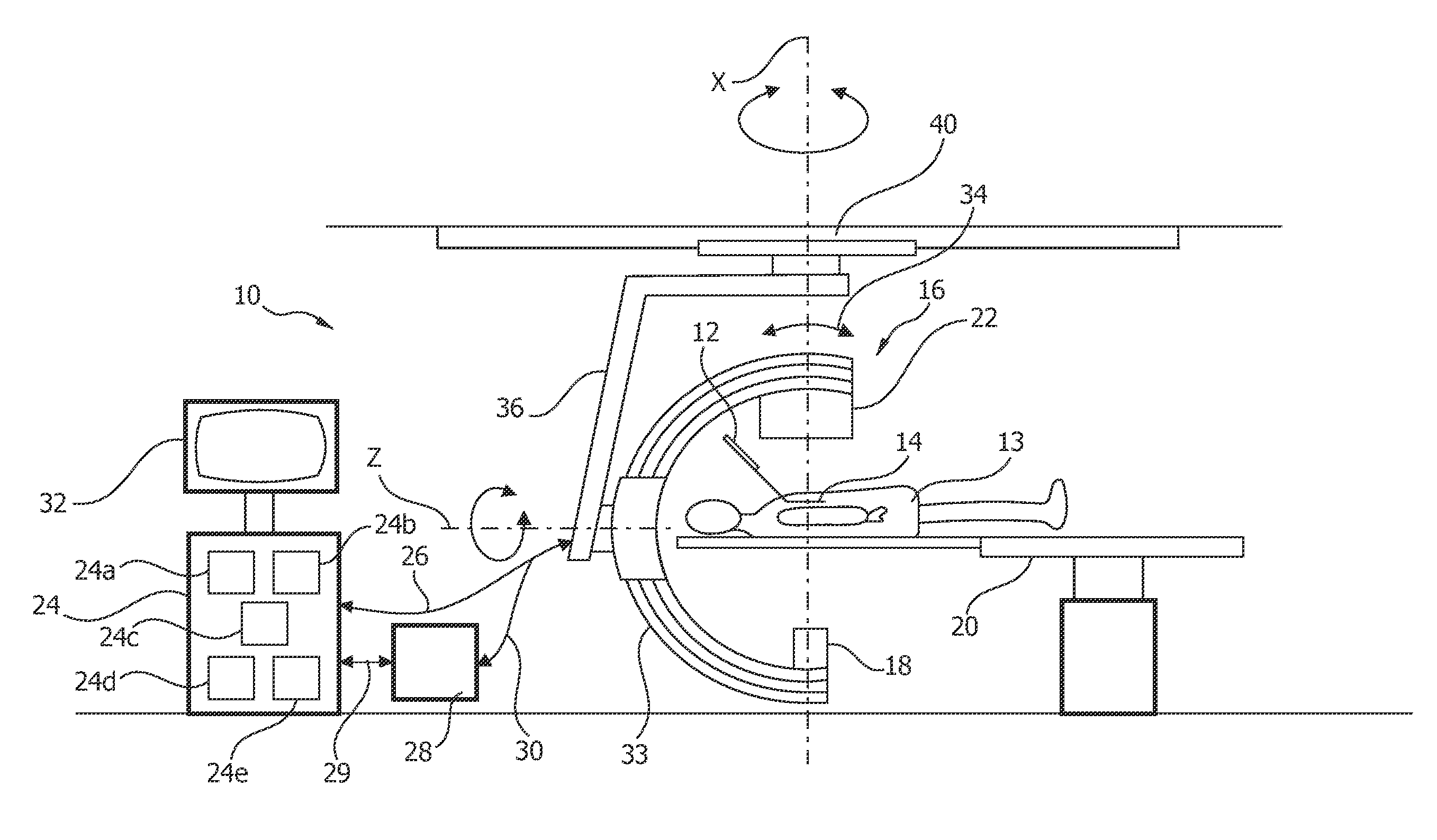
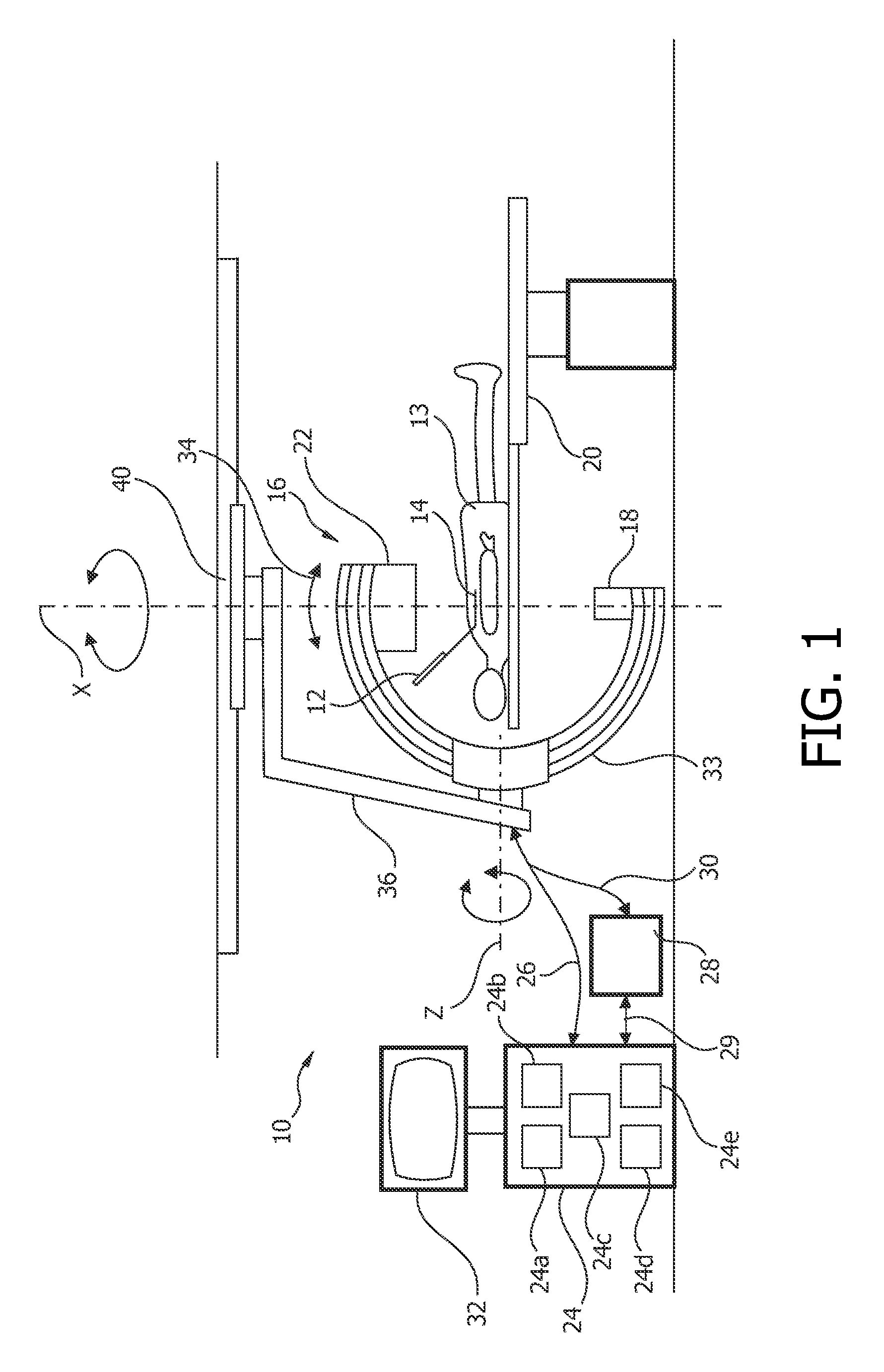
[0140]FIG. 1 schematically shows a system 10 for producing an image of a physical object, for example a stent inserted by an interventional device 12 in a vessel, for example a cardiac vessel, of a patient 14. As an example, the interventional device 12 is a guide wire for inserting the stent.

[0141]The system 10 comprises an X-ray image acquisition device 16 with a source of X-ray radiation 18 provided to generate X-ray radiation. A table 20 is provided to receive a subject to be examined, for example the patient 14. Further, the X-ray image acquisition device 16 comprises a detection module 22 located opposite the source of X-ray radiation 18. During the radiation procedure, the subject or patient 14 is located between the source of X-ray radiation 18 and the detection module 22. The latter is sending data to a control unit or processing arrangement 24 connected to the X-ray image acquisition device 16 by a cable connection 26. Of course, the cable connection 26 can also be provide...


PUM


Abstract

The invention relates to a system and a method for producing an image of a physical object and to a computer program element and a computer readable medium. In order to provide improved stent boost subtract also showing wire state information, a system and a method are provided, the method comprising the following steps: a) tracking a predetermined first feature (126) and a predetermined second feature (128) in a first plurality (114) of first images (116), which images reveal a first criterion (118); and determining a first feature transform; and determining second feature distortion vector fields relative to the first feature transform; b) associating and recording second feature distortion vector fields corresponding to at least two phase attributes (120); c) tracking the predetermined first feature (126) in at least one secondary image (142) which image reveals a second criterion; d) determining a first-feature-based inter-criterion the first-feature-based inter-phase transform and the second feature distortion vector fields corresponding to a matching phase attribute (120); and f) generating a combined inter-criterion image (162) based on the restored physical distortion.

Description

FIELD OF THE INVENTION[0001]The invention relates to producing an image of a physical object. In particular, the invention relates to a system and a method for producing an image of a physical object and to a computer program element and a computer readable medium.BACKGROUND OF THE INVENTION[0002]Methods for producing an image of a physical object are widespread in several technical fields, e.g. in the medical field. One example in the medical field for visualizing a physical object in an image is the field of coronary stents. For providing a user, e.g. a physician or a surgeon or an interventional cardiologist, information about whether the stent is in a correct position or whether the stent is correctly expanded and well apposed to the vessel walls, an image of the stent is produced and provided that is displayed to the user. It is very important to determine whether or not a stent is correctly deployed since incorrect deployment or partial expansion is a strong factor of re-steno...

Claims


Application Information

Patent Timeline
Patent Type & Authority Applications(United States)
IPC IPC(8): G06K9/00
CPCG06T7/003G06T2207/30204G06T2207/30052G06T2207/20224G06T2207/30101G06T2207/10121G06T7/337A61B6/12A61B6/4441A61B6/487A61B6/504A61B6/5288
Inventor FLORENT, RAOULVAN DEN HOUTEN, PETER WILLEM
Owner KONINKLIJKE PHILIPS ELECTRONICS NV
Why Eureka
Try Eureka