Image forming apparatus with fixing unit
- Summary
- Abstract
- Description
- Claims
- Application Information
AI Technical Summary
Benefits of technology
Problems solved by technology
Method used
Image

Examples
example 1
[0107]FIG. 6 is a schematic view of an image forming apparatus according to an embodiment (Example 1-1). FIGS. 7A to 7D are schematic views of fixing units according to some embodiments. FIGS. 8A to 8C are schematic views of moving devices according to some embodiments. FIG. 9 is a schematic view of an image forming apparatus according to another embodiment (Example 1-2). FIG. 10 is a schematic view of an image forming apparatus according to another embodiment (Example 1-3). FIG. 11 is a schematic view of an image forming apparatus according to another embodiment (Example 1-4). FIG. 12 is a schematic view of an image forming apparatus according to another embodiment (Example 1-5). FIG. 13 is a schematic view of an image forming apparatus according to another embodiment (Example 1-6).
[0108]In these embodiments, a black toner for forming black-and-white images employs the pressure-induced phase transition resin toner, and the heat fixing device 30 having the heat fixing nip and the pr...
example 1-1
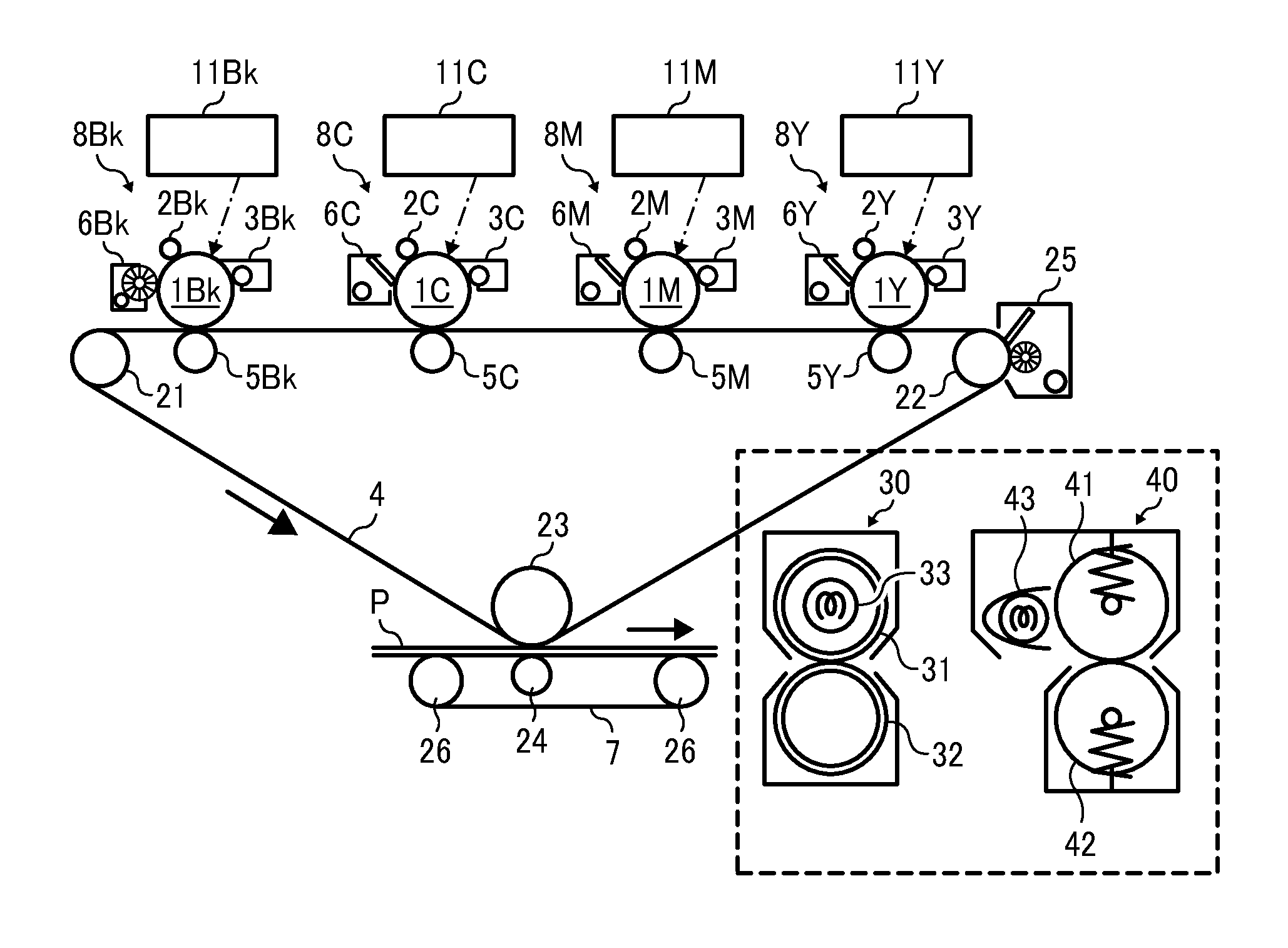
[0116]The image forming apparatus of Example 1-1, illustrated in FIG. 6, has the same configuration as that illustrated in FIG. 4.
[0117]Referring to FIG. 6, the imaging units 8Y, 8M, and 8C are disposed along an upper surface of the intermediate transfer medium 4 in this order from an upstream side thereof relative to the direction of movement of the intermediate transfer medium 4. The imaging units 8Y, 8M, and 8C contain thermoplastic resin toners for forming images of yellow, magenta, and cyan, respectively. The imaging unit 8Bk containing a pressure-induced phase transition resin toner for forming black image is disposed at the most downstream side relative to the direction of movement of the intermediate transfer medium 4. The photoreceptor cleaners 6Y, 6M, and 6C are disposed around the photoreceptors 1Y, 1M, and 1C, respectively. The photoreceptor cleaners 6Y, 6M, and 6C are adapted to remove residual thermoplastic resin toner particles from the photoreceptors 1Y, 1M, and 1C, ...
example 1-2
[0131]Example 1-2 is different from Example 1-1 in that the imaging unit 8Bk containing the black pressure-induced phase transition resin toner is brought into operation even in the color mode.
[0132]Referring to FIG. 9, the imaging unit 8Bk containing the black pressure-induced phase transition resin toner is disposed at the most upstream side of an upper surface of the intermediate transfer medium 4 relative to the direction of movement of the intermediate transfer medium 4. The imaging units 8Y, 8M, and 8C containing the thermoplastic resin toners of yellow, magenta, and cyan, respectively, are disposed along the upper surface of the intermediate transfer medium 4 in this order at a downstream side from the imaging unit 8Bk relative to the direction of movement of the intermediate transfer medium 4. Thus, the thermoplastic resin toners of yellow, magenta, and cyan transferred from the respective photoreceptors 1Y, 1M, and 1C onto the intermediate transfer medium 4 are prevented fr...
PUM
 Abstract
Description
Claims
Application Information
 - R&D Engineer
- R&D Manager
- IP Professional
- Industry Leading Data Capabilities
- Powerful AI technology
- Patent DNA Extraction
Browse by: Latest US Patents, China's latest patents, Technical Efficacy Thesaurus, Application Domain, Technology Topic.
© 2024 PatSnap. All rights reserved.Legal|Privacy policy|Modern Slavery Act Transparency Statement|Sitemap