
Methods and systems for common rail fuel system dynamic health assessment

Inactive Publication Date: 2013-01-10
GE GLOBAL SOURCING LLC
View PDF23 Cites 36 Cited by
  • Summary
  • Abstract
  • Description
  • Claims
  • Application Information

AI Technical Summary

Benefits of technology

The patent text describes a method for predicting the position of an inlet metering valve in a fuel system based on the current measured through the valve. This allows for the detection of fuel leaks and the failure of components without the need for specialized sensors. The method is adaptable for different engines and fuel systems. Overall, this technology improves fuel system monitoring and detection of faults.

Problems solved by technology

Disparities in the predicted current versus actual current indicate that a fuel flow unaccounted for in the flow balance model may exist, such as due to a leak.
Alternatively, disparities between predicted and actual current can indicate that a component has failed (e.g., a high pressure fuel pump (HPP) has excessive wear).

Method used


Image

  • Methods and systems for common rail fuel system dynamic health assessment
  • Methods and systems for common rail fuel system dynamic health assessment
  • Methods and systems for common rail fuel system dynamic health assessment

Examples


Embodiment Construction

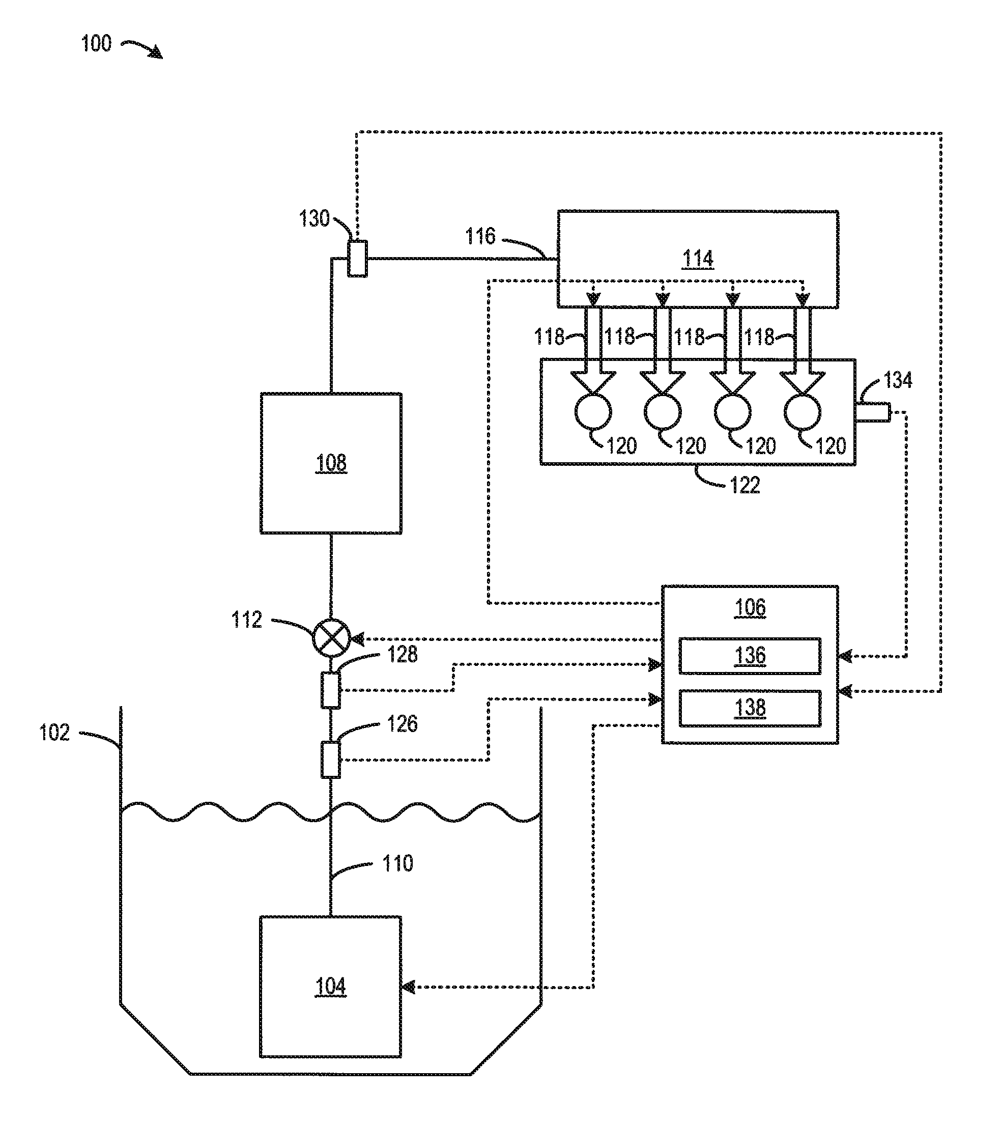
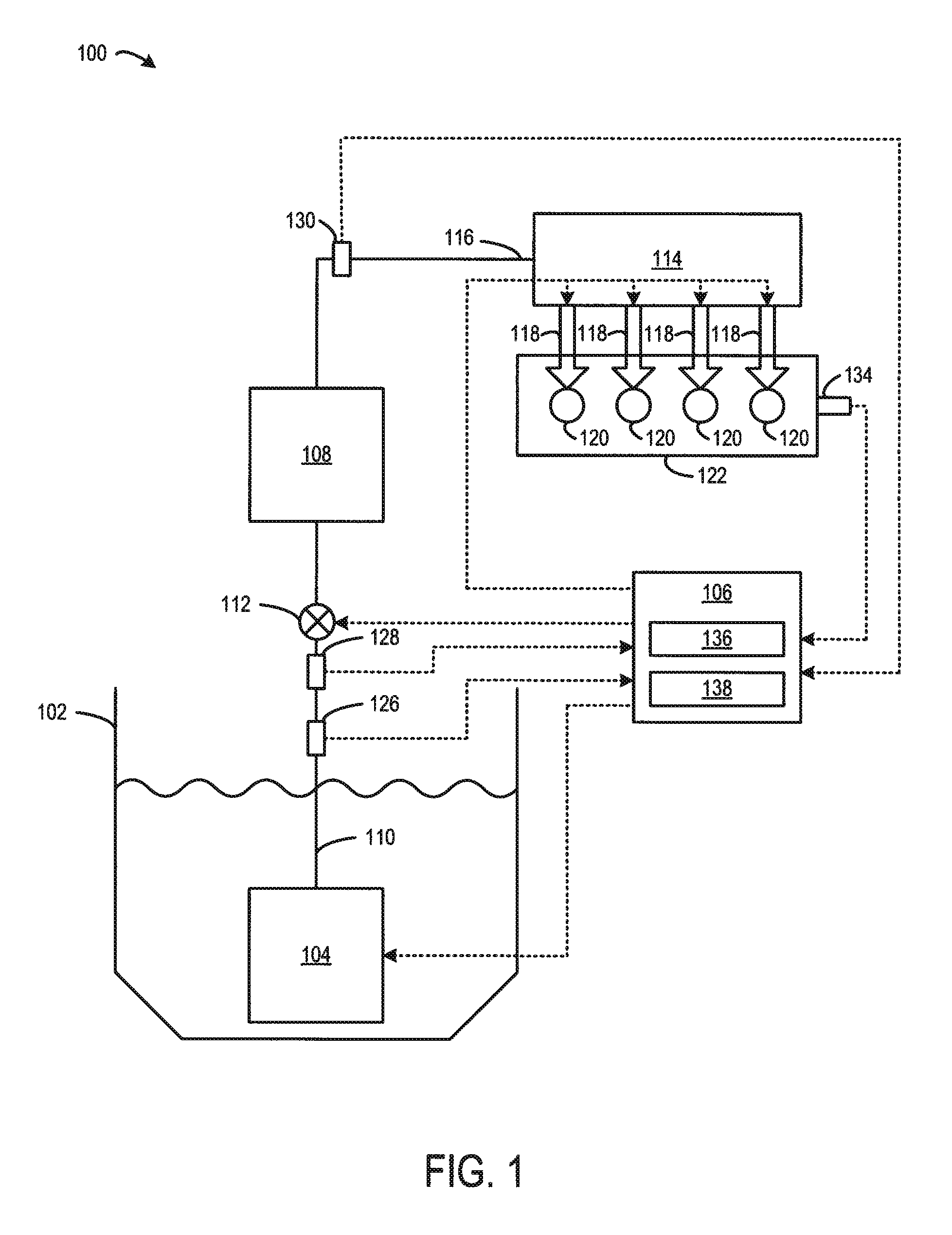
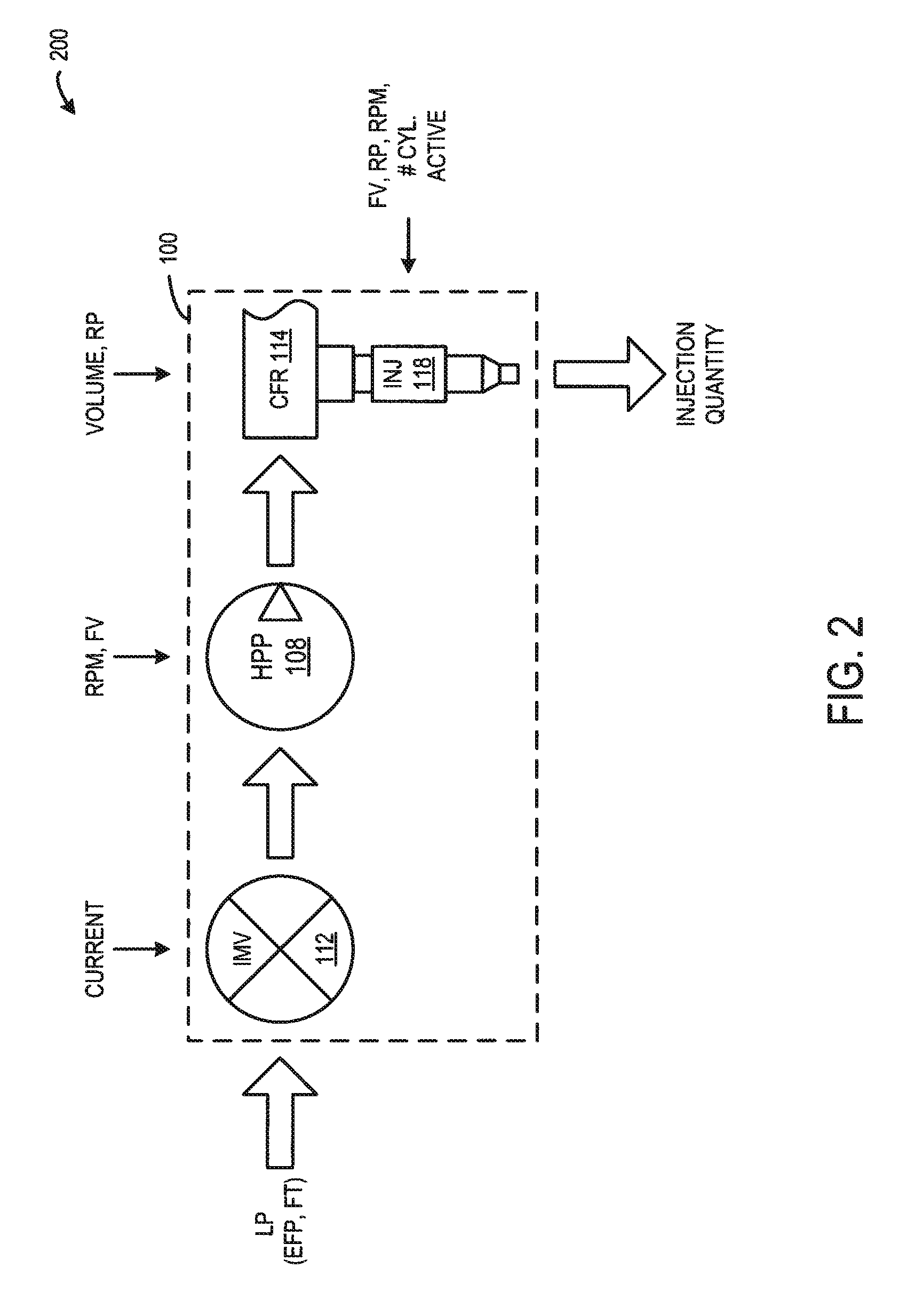
[0015]The present description relates to vehicles, such as rail vehicles, that include an engine (such as a diesel engine) where fuel is provided to the engine through a common rail fuel system (CRS). The CRS includes a common fuel rail that provides fuel to a plurality of fuel injectors for fuel injection into cylinders of the engine. In one example, the CRS includes an inlet metering valve (IMV) that is positioned between a low-pressure fuel pump and a high-pressure fuel pump. The IMV is operable to control fuel flow to the high-pressure fuel pump that supplies the common fuel rail with fuel. The IMV can be adjusted to vary an amount of fuel provided to the common fuel rail as operation conditions change. More particularly, the present description is related to dynamically assessing the health of the CRS.

[0016]For example, the health of the CRS can be dynamically assessed through various approaches for detecting fuel leaks in the CRS. One embodiment of a CRS is shown in FIG. 1.

[00...


PUM


Abstract

Fuel control dynamic health assessment systems and methods related to monitoring fuel flow control are provided. In one embodiment, a method for controlling a system having an engine, includes determining a predicted valve position of a valve, the valve being operable to control fuel flow to a fuel pump that pumps fuel to a common fuel rail of the engine, determining an actual valve position, determining an error between the predicted valve position and the actual valve position, and setting a degradation condition in response to the error.

Description

FIELD[0001]The subject matter disclosed herein relates to methods and systems for controlling a common rail fuel system in a vehicle.BACKGROUND[0002]Vehicles, such as rail vehicles, include power sources, such as diesel engines. In some vehicles, fuel is provided to the diesel engine by a common rail fuel system. One type of common rail fuel system comprises a low-pressure fuel pump in fluid communication with a high-pressure fuel pump, and a fuel rail in fluid communication with the high-pressure fuel pump and further in fluid communication with at least one engine cylinder. The high-pressure fuel pump pressurizes fuel for delivery through the fuel rail. Fuel travels through the fuel rail to at least one fuel injector, and ultimately to at least one engine cylinder where fuel is combusted to provide power to the vehicle. In order to reduce the likelihood of engine degradation, the common rail fuel system may be monitored for fuel leaks.[0003]In one approach, the common rail fuel sy...

Claims


Application Information

Patent Timeline
IPC IPC(8): F02D41/26F02D28/00
CPCF02D41/22F02D41/3845F02D2041/2058F02D2041/224F02M37/0047F02D41/2464F02D2200/0602F02D2200/063F02D2041/225
Inventor NISTLER, PAUL GERARDGOEL, NIKITA
Owner GE GLOBAL SOURCING LLC
Learn More