
Emission control system for a vehicle

a technology of emission control system and vehicle, which is applied in the direction of machine/engine, water supply installation, pipe heating/cooling, etc., can solve the problems of affecting the proper inhibiting or preventing the refilling of the reservoir, and affecting the operation of the scr system

Inactive Publication Date: 2013-01-17
GM GLOBAL TECH OPERATIONS LLC
View PDF8 Cites 1 Cited by
  • Summary
  • Abstract
  • Description
  • Claims
  • Application Information

AI Technical Summary

Benefits of technology

The patent describes a system and method for controlling emissions in a vehicle. It involves heating and pumping a reductant (a substance that helps reduce emissions) from a reservoir to the engine. This melts any frozen reductant in the intake pipe, which prevents clogging and ensures a steady supply of reductant for combustion. The technical effect is improved engine performance and control over emissions levels.

Problems solved by technology

Generally, the reductant has a freezing temperature in the range of 12 degrees Fahrenheit (−11 degrees Celsius), which may present challenges to the proper operation of the SCR system in cold weather.
However, the reductant is also known to freeze at the reservoir intake pipe (fill pipe), which can inhibit or prevent refilling of the reservoir until the frozen reductant melts.
Low profile reductant reservoirs are particular susceptible to intake pipe freeze.

Method used


Image

  • Emission control system for a vehicle
  • Emission control system for a vehicle
  • Emission control system for a vehicle

Examples


Embodiment Construction

[0011]The following detailed description is merely exemplary in nature and is not intended to limit the subject matter of the disclosure or its uses. Furthermore, there is no intention to be bound by any expressed or implied theory presented in the preceding technical field, background, brief summary or the following detailed description.

[0012]The following description refers to elements or features being “connected” or “coupled” together. As used herein, “connected” may refer to one element / feature being directly joined to (or directly communicating with) another element / feature, and not necessarily mechanically. Likewise, “coupled” may refer to one element / feature being directly or indirectly joined to (or directly or indirectly communicating with) another element / feature, and not necessarily mechanically. However, it should be understood that, although two elements may be described below, in one embodiment, as being “connected,” in alternative embodiments similar elements may be ...


PUM


Abstract

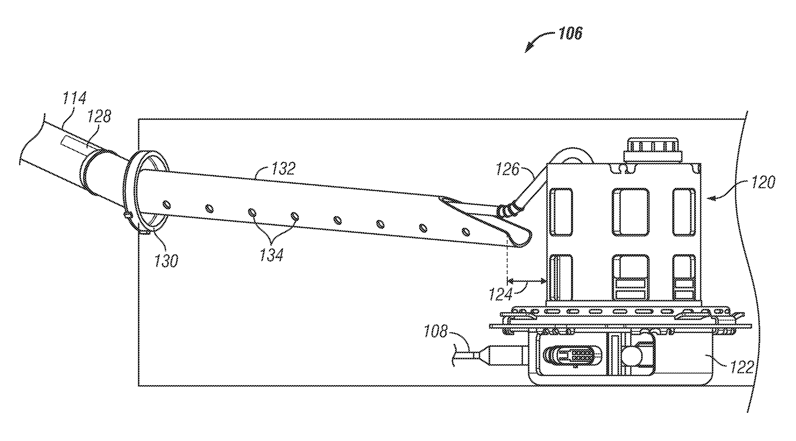
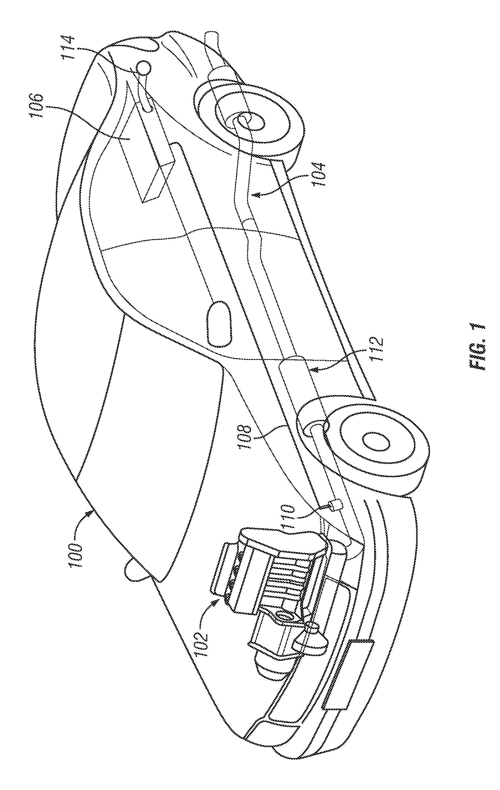
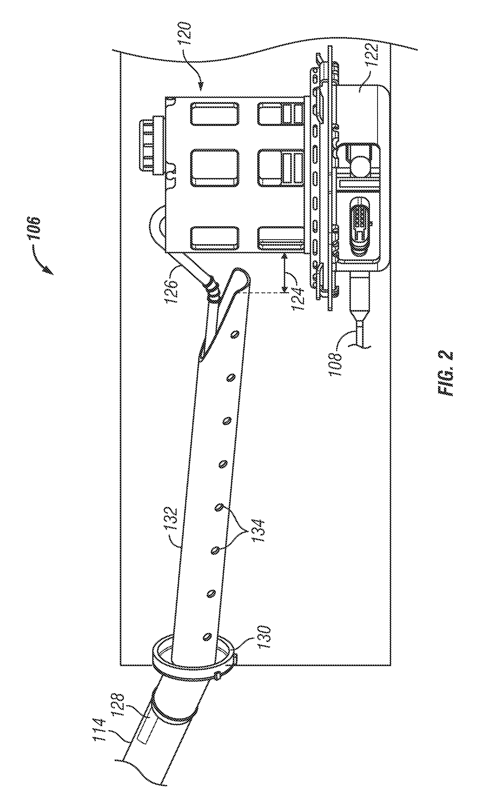
In accordance with an exemplary embodiment, an emission control system and method is provided for a vehicle. The system comprises a reductant reservoir having an intake pipe for receiving reductant and a heater for heating the reductant. A pump provides the heated reductant to an injector and also to a conduit extending into the intake pipe to provide heated reductant into the intake pipe to melt any frozen reductant in the intake pipe. The method comprises heating reductant stored within a reservoir of a vehicle emission control system, and pumping the heated inductant into an intake pipe of the reservoir to melt any frozen reductant in the intake pipe.

Description

TECHNICAL FIELD[0001]The technical field generally relates to an emission control system for vehicles with diesel engines and, more particularly to an improved reductant storage system for the emission control system.BACKGROUND[0002]Current emission control regulations necessitate the use of catalysts in the exhaust systems of vehicles in order to convert regulated exhaust constituents such as carbon monoxide (CO), hydrocarbons (HC) and oxides of nitrogen (NOx) into unregulated exhaust gas. Accordingly, vehicles with diesel-powered engines employ a process known as Selective Catalytic Reduction (SCR), in which nitrogen oxide (NOx) vehicle emissions are ultimately reduced into nitrogen (N), water (H2O) and carbon dioxide (CO2). In the SCR process, a reductant (commonly referred to as “Diesel Emissions Fluid” or DEF) consisting of a solution of about 32.5 percent automotive-grade urea and purified water is sprayed as a mist into the high-temperature exhaust stream, where the reductant...

Claims


Application Information

Patent Timeline
Patent Type & Authority Applications(United States)
IPC IPC(8): F01N3/18F16K49/00F01N3/20
CPCF01N3/2066F01N2610/02Y02T10/24F01N2610/1406F01N2610/1486F01N2610/14Y10T137/6416Y10T137/0318Y02A50/20Y02T10/12
Inventor BASISTA, JEFFREY S.YACCARINO, PHILIP A.
Owner GM GLOBAL TECH OPERATIONS LLC
Learn More