Heat exchanger for a high efficiency hot air heating appliance and heating appliance equipped therewith

a heat exchanger and high-efficiency technology, applied in the direction of energy-efficient heating/cooling, air heaters, sustainable buildings, etc., can solve the problems of relatively high cost of collectors, difficult to optimise assembly, and relatively complex assembly of collectors, etc., and achieve the effect of easy optimization

Active Publication Date: 2013-01-17
MULTICALOR IND
View PDF1 Cites 11 Cited by
  • Summary
  • Abstract
  • Description
  • Claims
  • Application Information

AI Technical Summary

Benefits of technology

This patent describes a heat exchanger assembly that is designed to be easy to optimize and can be positioned in different ways without collecting too much condensation. The primary and secondary heat exchangers are built at the same time, allowing for more flexibility in the orientation of the assembly.

Problems solved by technology

A disadvantage of such a heat exchanger is that its assembly is relatively complex and consists of relatively many constituent components.
A disadvantage of such heat exchangers is that the assembly is difficult to optimise.
This collector is relatively expensive as it is generally manufactured from stainless steel.

Method used


Image

  • Heat exchanger for a high efficiency hot air heating appliance and heating appliance equipped therewith
  • Heat exchanger for a high efficiency hot air heating appliance and heating appliance equipped therewith
  • Heat exchanger for a high efficiency hot air heating appliance and heating appliance equipped therewith

Examples


Embodiment Construction

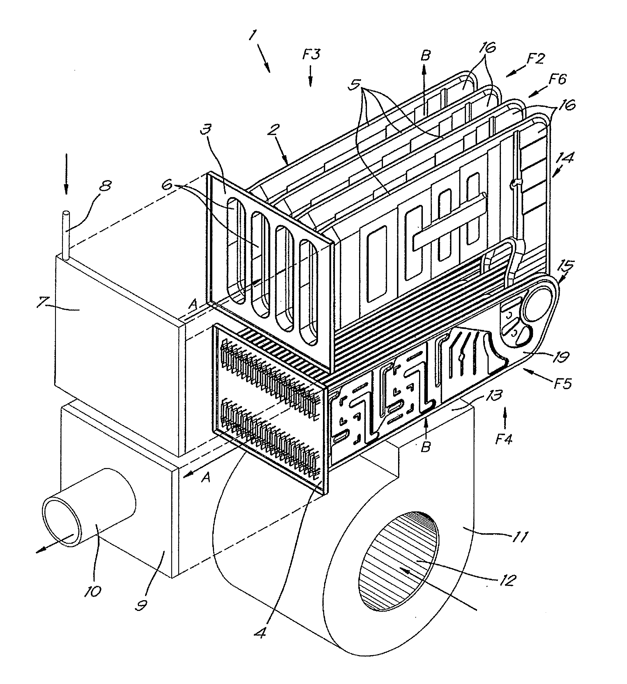
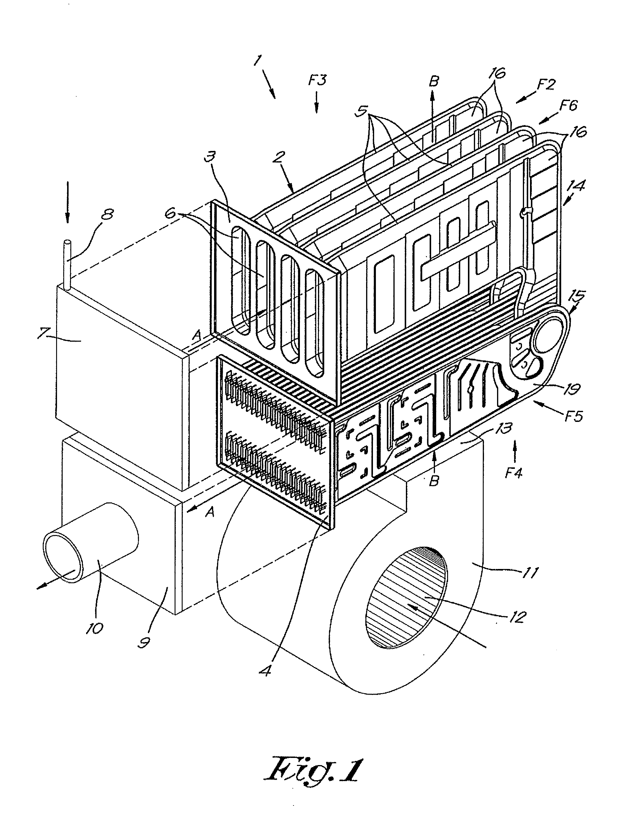
[0043]The high efficiency hot air heating appliance 1 shown in FIG. 1 essentially consists of a heat exchanger 2 that is provided with an inlet 3 and an outlet 4 and which in this case is constructed from a number of segments 5 that each define a flow channel 6; a burner 7 positioned opposite the inlet 3 with a supply 8 for fuel or a mixture of fuel and air for the production of hot combustion gases that are driven through the heat exchanger 2 in the direction of the arrows A; an outlet collector 9 into which the aforementioned outlet 4 flows and which is provided with an exhaust pipe 10 for connection to a chimney or similar.

[0044]Furthermore the heating appliance 1 is equipped with a fan 11 that can draw in the surrounding air via an input 12 and which is intended to blow the air drawn in via an outlet 13 over the segments 5 of the heat exchanger 1, as indicated by the arrows B.

[0045]In this way the air flowing over the segments 5 is heated, so that the heated air can be used for ...


PUM


Abstract

Heat exchanger for a high efficiency hot air heating appliance (1), with at least one segment (5) and with a primary section (14) and, viewed in the flow direction (A), followed by a secondary condensing section (15), whereby the segment (5) consists of at least one primary element (16) and at least two secondary condensing elements (19), that form part of the secondary condensing section (15) of the segment (5), and the inputs (20) of each of them are connected in parallel to the output (18) of the primary element (16) in such a way that the gas flow coming from the primary element (16) is divided over the secondary condensing elements (19) connected to it.

Description

[0001]This application claims the benefit of provisional application No. 61 / 507,743 filed Jul. 14, 2011, the entirety of which is incorporated by reference.FIELD OF THE INVENTION[0002]The present invention relates to a heat exchanger for a high efficiency hot air heating appliance.[0003]Such appliances produce an airflow that is heated in the appliance, and which is used to heat a building for example.BACKGROUND OF THE INVENTION[0004]Such heating appliances consist, in a known way, of a burner to produce hot combustion gases to heat the airflow, whereby the combustion gases are guided through one or more elements that each form a flow channel with an inlet and outlet for these gases, while the airflow to be heated, for example originating from a fan, is guided along the outside of these elements.[0005]Thereby heat transfer occurs from the combustion gases to the airflow, whereby the temperature of the combustion gases decreases from the inlet to the outlet.[0006]With high efficiency...

Claims


Application Information

Patent Timeline
IPC IPC(8): F24H3/10F28F3/12F28F17/00
CPCF24H3/105F24H8/00F28F3/12F24D2220/06Y02B30/102F24H3/087F28D9/0056Y02B30/00
Inventor TOLLENEER, STEVENVERBERCK, MARCEL FRANCISCUS J.
Owner MULTICALOR IND
Why Eureka
Try Eureka