Tread for a pneumatic tire

a pneumatic tire and tread technology, applied in the field of pneumatic tires, can solve the problems of loss of treadwear, poor treadwear of tires, and noisy noise of tires

Inactive Publication Date: 2013-01-17
GEOR FRANCOIS PIERRE CHARLES GERARD +3
View PDF3 Cites 13 Cited by
  • Summary
  • Abstract
  • Description
  • Claims
  • Application Information

AI Technical Summary

Benefits of technology

[0017]A pneumatic tire in accordance with the present invention includes a pair of annular bead cores, a carcass extending around the bead cores to form a toroidal structure, a belt reinforcing structure radially outward of the carcass, and a circumferentially extending tread radially outward of the belt reinforcing structure. The tread includes a first circumferentially continuous groove, a second circumferentially continuous groove, a third circumferentially continuous groove, a fourth circumferentially continuous groove, a central rib interposed between the second and third axially inner circumferentially continuous grooves, the central rib extending continuously around a circumference of the tread, a first middle rib interposed between the first and second grooves, the first middle rib extending continuously around the circumference of the tread, a second middle rib interposed between the third and fourth grooves, the second middle rib extending continuously around the circumference of the tread, a first circumferentially extending shoulder rib disposed laterally outside of the first circumferentially continuous groove, and a second circumferentially extending shoulder rib disposed laterally outside of the fourth circumferentially continuous groove. The central rib has a plurality of circumferentially spaced sipes originating at the second circumferentially continuous groove and extending axially and circumferentially across the central rib to the third circumferentially continuous groove. The first middle rib has a plurality of circumferentially spaced sipes originating at the second inner circumferentially continuous groove and extending axially and circumferentially across the first middle rib to the third circumferentially continuous groove. The second middle rib has a plurality of circumferentially spaced sipes originating at the third inner circumferentially continuous groove and extending axially and circumferentially across the second middle rib to the fourth circumferentially continuous groove.
[0018]According to another aspect of the pneumatic tire, the first groove has an axial width decreasing from a surface of the first shoulder rib radially inward toward an axis of rotation of the tire.
[0019]According to still another aspect of the pneumatic tire, the fourth groove has an axial width decreasing from a surface of the second shoulder rib radially inward toward an axis of rotation of the tire.

Problems solved by technology

However, these tires have been noisy with poor treadwear when driven at highway speeds on paved roads.
Lateral grooves may be limited, since lateral grooves may accelerate treadwear.
Voids, such as grooves, may provide traction, but a consequential loss of treadwear may result because the net-road contacting area of the tread is reduced by the use of grooves.
Further, lateral grooves may create an entry / exit point into / out of the contact patch of the tread thereby initiating additional heel / toe wear.
While these treads wear generally well, irregular wear along the edges of the circumferentially continuous grooves may occur.

Method used


Image

  • Tread for a pneumatic tire
  • Tread for a pneumatic tire
  • Tread for a pneumatic tire

Examples


Embodiment Construction

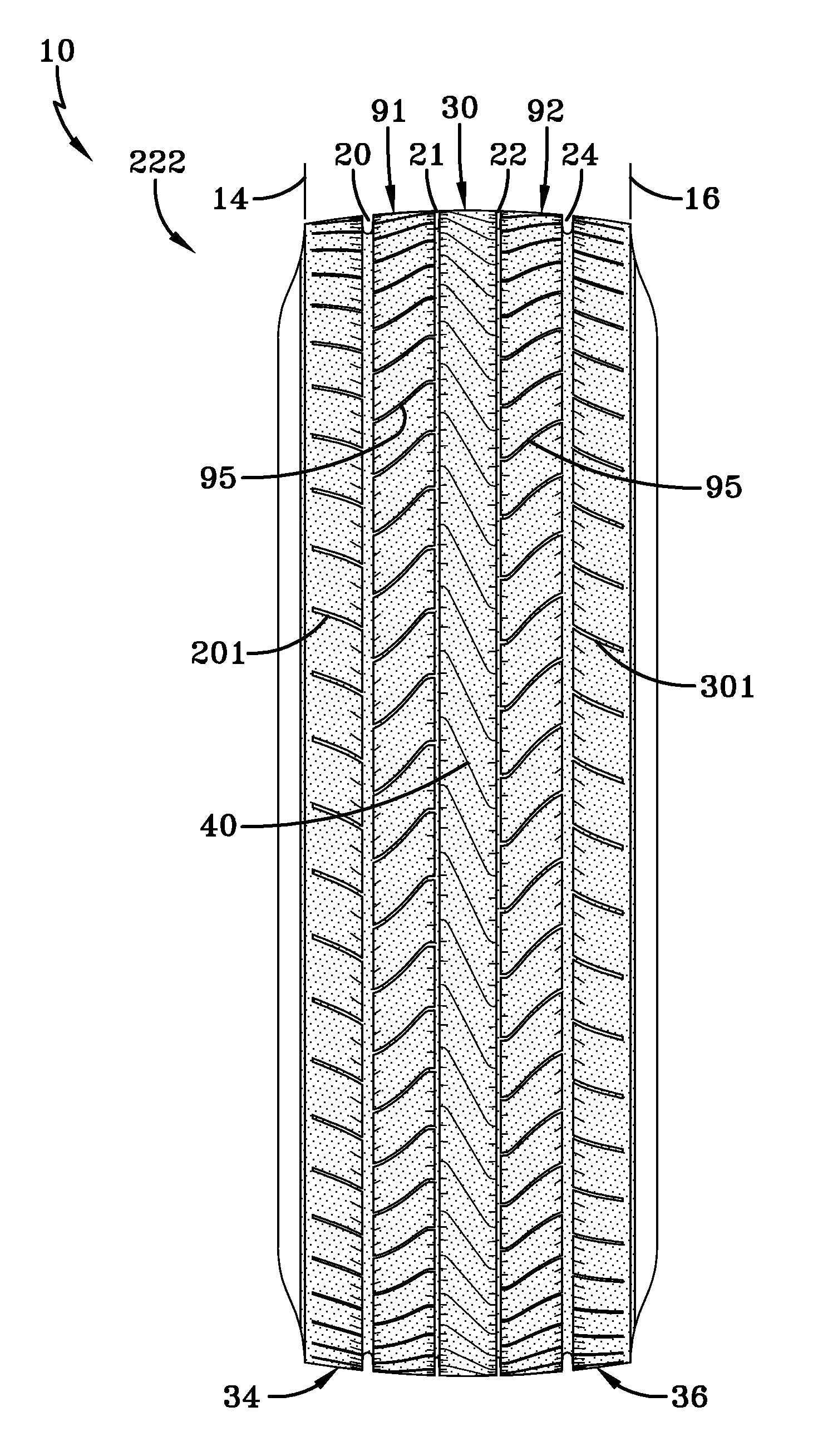
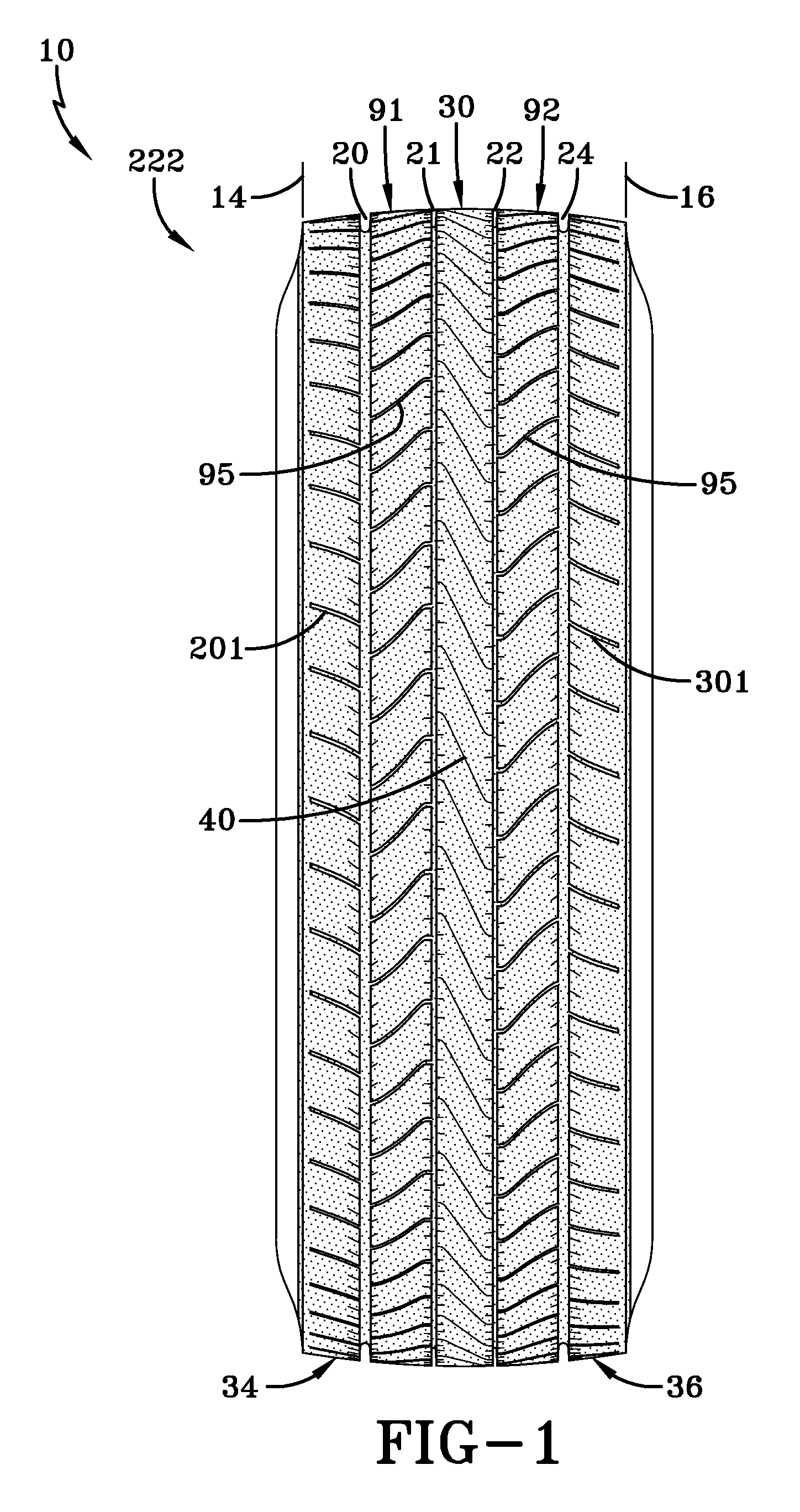
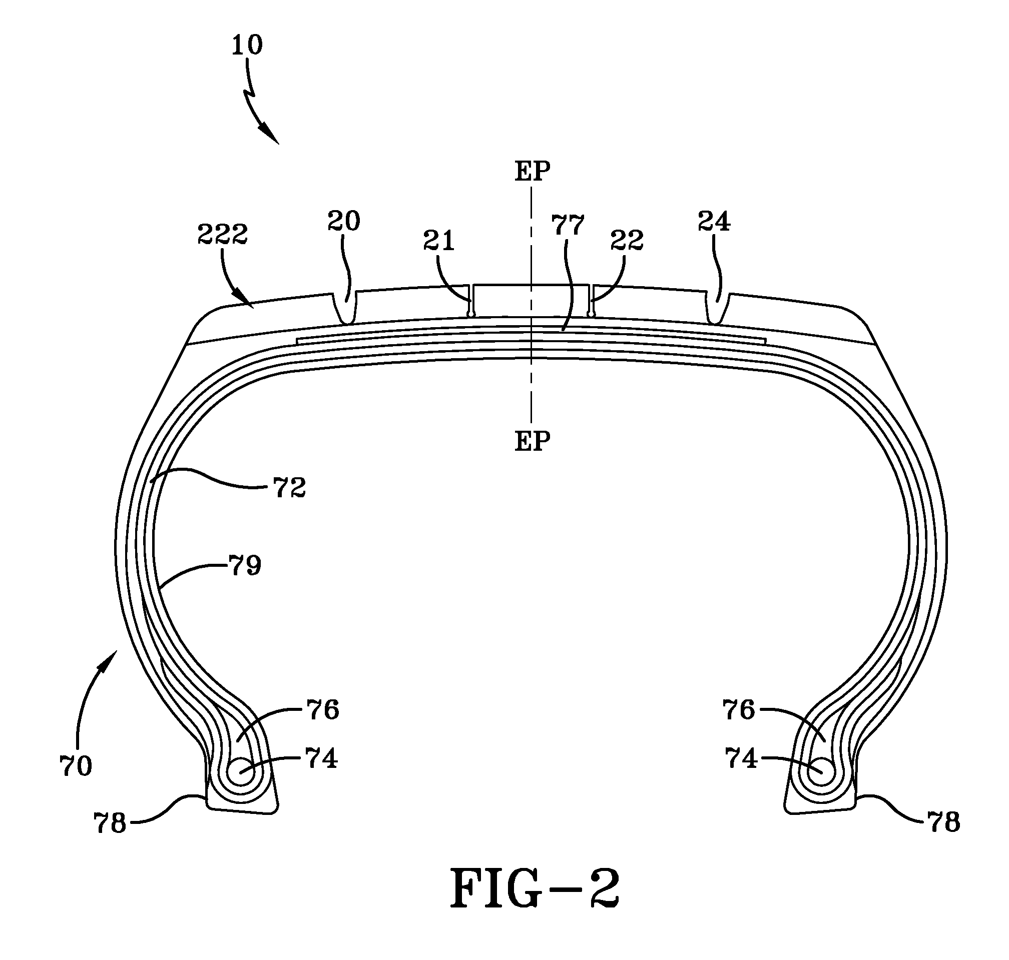
[0094]With the reference to FIGS. 1-3, a pneumatic tire (10) having a tread (222) according to one example of the present invention is shown. The tread (222) may have an axis of rotation R and first and second lateral edges (14, 16). The tread (222), when used with the pneumatic tire (10), may employ a tire having a carcass (70) with one or more plies (72) reinforced by radially extending synthetic or metal cords and a pair of substantially inextensible bead cores (74), an apex (76) radially above the bead cores (74), and a belt reinforcing structure (77) radially outward of the plies (72). The tire (10) may have an air impervious halobutyl liner (79) and a pair of rubber chafers (78).

[0095]While the carcass (70) and other structures contribute much to the performance of the pneumatic tire (10), the example tread (222) of FIG. 1 may have four circumferentially continuous grooves (20, 21, 22, 24). Interposed between the two axially inner circumferentially continuous grooves (21, 22) ...


PUM


Abstract

A tread for a pneumatic tire includes a first circumferentially continuous groove, a second circumferentially continuous groove, a third circumferentially continuous groove, a fourth circumferentially continuous groove, a central rib interposed between the second and third axially inner circumferentially continuous grooves, a central rib, a first middle rib, a second middle rib, a first shoulder rib, and a second shoulder rib. The central rib extends continuously around a circumference of the tread. The first middle rib is interposed between the first and second grooves. The first middle rib extends continuously around the circumference of the tread. The second middle rib is interposed between the third and fourth grooves. The second middle rib extends continuously around the circumference of the tread. The first circumferentially extending shoulder rib is disposed laterally outside of the first circumferentially continuous groove. The second circumferentially extending shoulder rib is disposed laterally outside of the fourth circumferentially continuous groove. The central rib has a plurality of circumferentially spaced sipes originating at the second circumferentially continuous groove and extending axially and circumferentially across the central rib to the third circumferentially continuous groove. The first middle rib has a plurality of circumferentially spaced sipes originating at the second inner circumferentially continuous groove and extending axially and circumferentially across the first middle rib to the third circumferentially continuous groove. The second middle rib has a plurality of circumferentially spaced sipes originating at the third inner circumferentially continuous groove and extending axially and circumferentially across the second middle rib to the fourth circumferentially continuous groove.

Description

TECHNICAL FIELD[0001]The present invention relates to a pneumatic tire, and more particularly, to a tread for a pneumatic tire.BACKGROUND ART[0002]Pneumatic truck tires constructed for slippery or even winter driving conditions are intended to be suitable for running on surfaces of reduced compactness such as snow-covered roadways. Such tires are required to demonstrate suitable traction (gripping), power, braking, and handling characteristics on wet or snow covered surfaces while maintaining rolling resistance and mileage performance. The tread pattern of commercial truck tires must accordingly meet such competing objectives in order to provide the user with acceptable tire performance.[0003]With the continuing rise in popularity of light trucks and cargo vans, there exists a need to provide tires that have the ability to be driven on paved roads while carrying heavy loads without excessive noise, yet also to be capable of being driven in heavy snow or wet roads. Often these tires ...

Claims


Application Information

Patent Timeline
Patent Type & Authority Applications(United States)
IPC IPC(8): B60C11/12
CPCB60C11/12B60C11/04B60C2200/06B60C2011/0348B60C11/1259B60C2011/0355B60C2011/1209B60C11/1281
Inventor GEORGES, FRANCOIS PIERRE CHARLES GERARDWINKIN, DIDIERBRAUN, LOTHARLE, PHUOC THUAN
Owner GEOR FRANCOIS PIERRE CHARLES GERARD
Why Eureka
Try Eureka