Eureka AIR delivers breakthrough ideas for toughest innovation challenges, trusted by R&D personnel around the world.

Traffic monitoring device

Active Publication Date: 2013-01-17
OPTEX CO LTD
View PDF3 Cites 4 Cited by
  • Summary
  • Abstract
  • Description
  • Claims
  • Application Information

AI Technical Summary

Benefits of technology

The present invention is a traffic monitoring device that can accurately determine the number of objects, such as human bodies, in a supervised sector without being affected by the shape of their hairstyles or flocking heads. It uses a template matching method to determine the number of objects based on the shape of the object and the distance measuring points within the blocks. The device can even determine the number of objects when multiple individuals pass by with their heads clung together. Additionally, the device can vary the threshold value of the number of distance measuring points or add a weighting to the pixels based on their imaging distance to increase accuracy when the camera is at a farther distance.

Problems solved by technology

It has been found that since the conventional technologies are such that the number of the objects is determined on the basis of the area or the volume, they are incapable of determining the number of objects accurately and with no error by the following reason.
Specifically, considering that the hairstyle of people differs greatly from person to person, and particularly where some people have a voluminous hairdo, it has often occurred that the head of such people cannot be accurately grasped under the influence of the particular hairstyle and that the determination of the number of objects often results in error because the shape of the object is not taken into consideration.
Also, in the case where a plurality of passers-by walk in crowds with their heads clung to each other, it is difficult to break up a crowd of those passers-by and it similarly often occurs that the number of them tends to be erroneously determined.

Method used


Image

  • Traffic monitoring device
  • Traffic monitoring device
  • Traffic monitoring device

Examples


Embodiment Construction

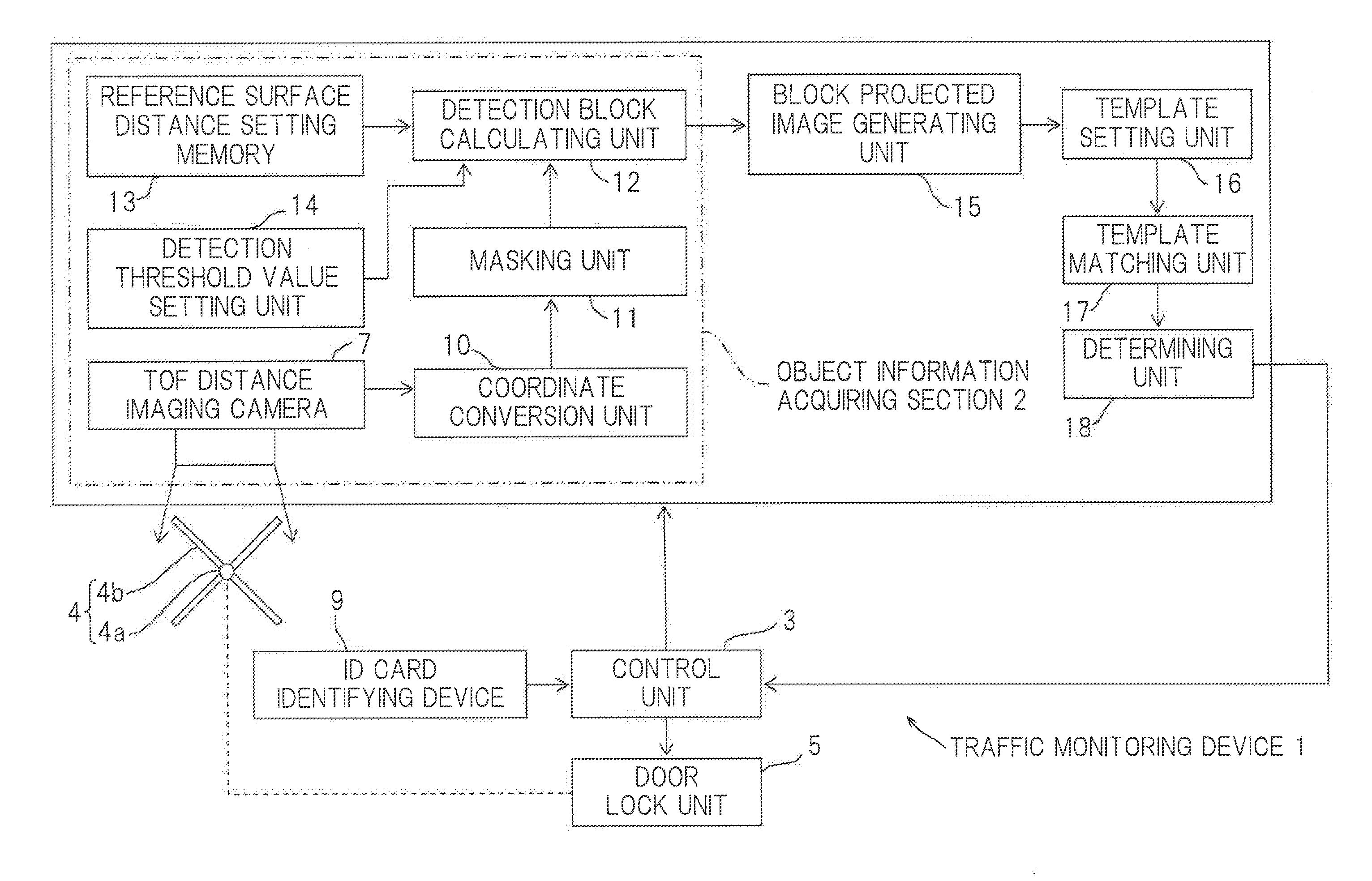
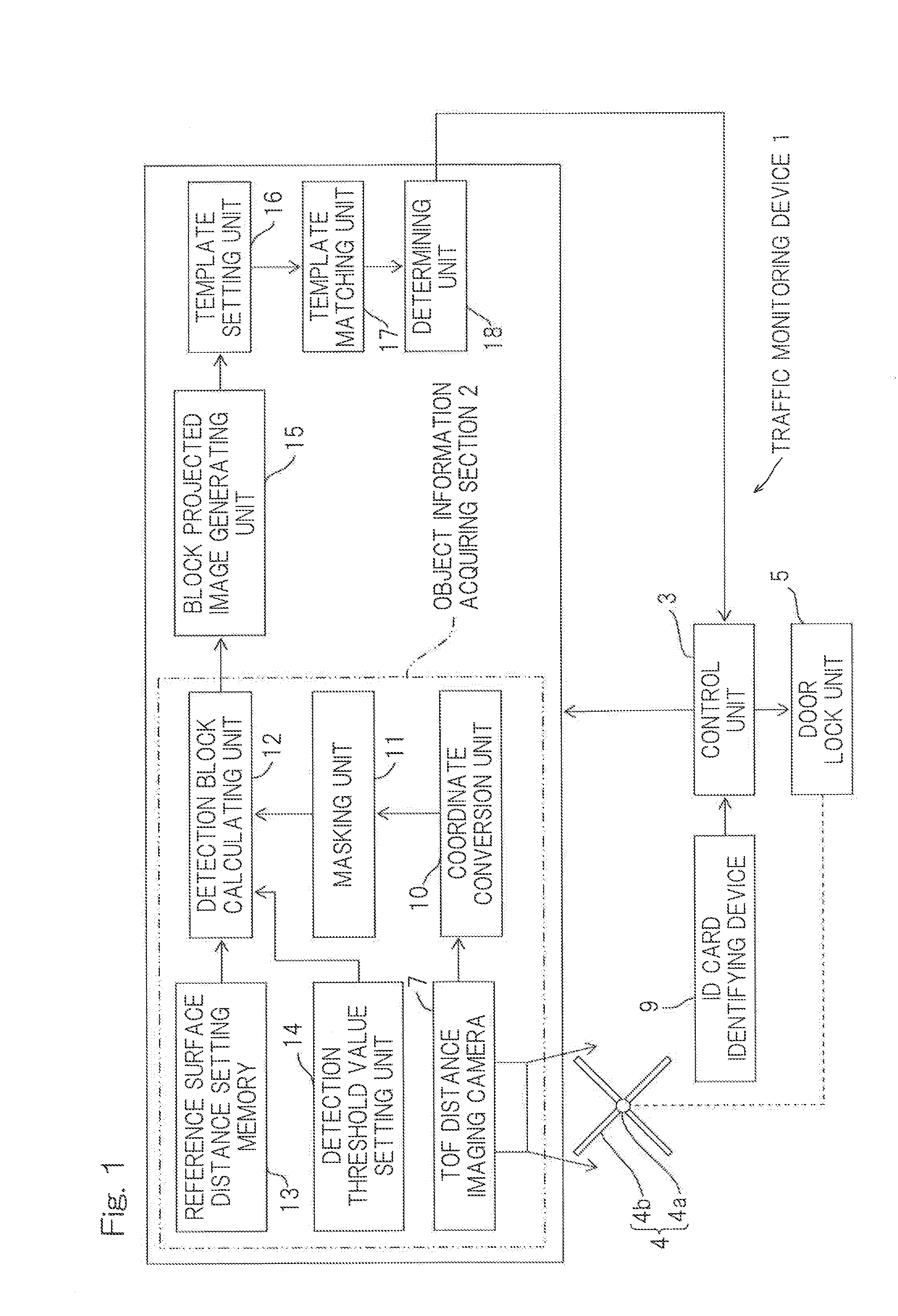
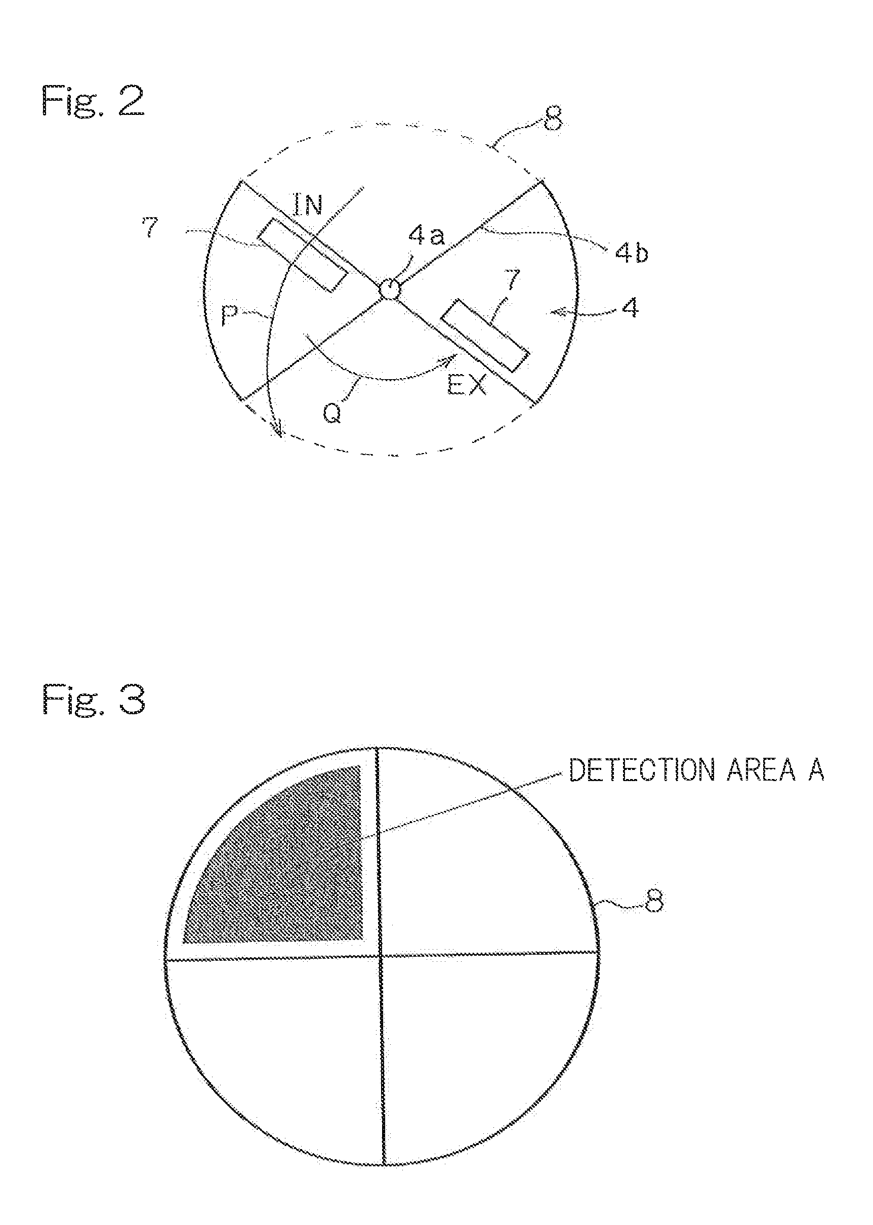
[0032]FIG. 1 illustrates a block diagram of a traffic monitoring device designed in accordance with one preferred embodiment of the present invention. A traffic monitoring device 1 for determining the number of objects from a three dimensional object information acquired in connection with objects present within a supervised sector to be monitored by the device includes a control unit 3 for controlling the operation of a revolving door 4 on the basis of the result of determination of the number of the objects and a door lock unit 5 adapted to be controlled by the control unit 3 to lock the revolving door 4. Accordingly, in describing the illustrated embodiment, reference is made by way of example to the traffic monitoring device used in monitoring the number of objects such as, for example, human bodies moving in a particular direction, shown by the arrow P, while the revolving door 4 shown in FIG. 2 is revolved in a direction shown by the arrow Q.

[0033]The revolving door 4 is of a ...


PUM


Abstract

A traffic monitoring device determines accurately the number of objects (H) such as, for example, human bodies present within a supervised sector (8), without being affected by influences of a clinging condition of a plurality of heads and / or hairdos. In determining the number of the objects (H), this traffic monitoring device performs a template matching with template blocks (20) of the shape of the objects (H), in which block areas including heads (α), hairdos buffer units (β) and shoulders (γ) are represented by template images, relative to the block projected image acquired from a three dimensional object information resulting from a detection block (B1) related to the objects (H) present within the supervised sector (8).

Description

[0001]CROSS REFERENCE TO THE RELATED APPLICATION[0002]This application is based on and claims Convention priority to Japanese patent application No. 2011-152658, filed Jul. 11, 2011, the entire disclosure of which is herein incorporated by reference as a part of this application.BACKGROUND OF THE INVENTION[0003]1. Field of the Invention[0004]The present invention relates to a traffic monitoring device for monitoring the number of objects such as, for example, passers-by then moving through a supervised sector defined at, for example, a doorway provided with a revolving door.[0005]2. Description of Related Art[0006]As a security technology for curbing the flow of information from a corporate building, it has become a recent wide spreading trend to install the authenticating device at an important doorway of the corporate building so that the door at the doorway can be opened only when the authenticating device identifies the bearer of an ID card or fingerprint by the ID card or finge...

Claims


Application Information

Patent Timeline
IPC IPC(8): G06K9/62
CPCG07C9/00G07C9/025G06K9/6203G06K9/00362G06K9/00778G07C9/15G06V40/10G06V20/53G06V10/7515
Inventor KAWAHATA, YASUTAKA
Owner OPTEX CO LTD
Why Eureka
Eureka Blog
Learn More