
Pulse wave velocity measurement device, pulse wave velocity measurement method and pulse wave velocity measurement program

a technology of pulse wave velocity and measurement method, which is applied in the field of pulse wave velocity measurement device, can solve the problems of inconvenient user sitting up and the device cannot ensure accurate measurement, so as to improve the convenience of users and accurate measurement of pulse wave velocity

Inactive Publication Date: 2013-01-17
SHARP KK
View PDF4 Cites 18 Cited by
  • Summary
  • Abstract
  • Description
  • Claims
  • Application Information

AI Technical Summary

Benefits of technology

The present invention provides a device for measuring the velocity of pulse waves that is accurate and not affected by the pressure caused by the person's position. This means that the measurement can be done without the need to lie still in asupine position. As a result, users can have more convenience, as they can measure in a sitting or upright position that is not supine.

Problems solved by technology

In consideration of scenes of use by a user, however, it is inconvenient for the user to be required to lie supinely every time for the measurement of the pulse wave velocity.
Thus the conventional pulse wave velocity measurement devices have a problem in that the devices cannot ensure accurate measurement because the pulse wave velocity is increased by hydrostatic pressure difference when the measurement is performed in the sitting position or the upright position, for instance, rather than in the supine position.

Method used


Image

  • Pulse wave velocity measurement device, pulse wave velocity measurement method and pulse wave velocity measurement program
  • Pulse wave velocity measurement device, pulse wave velocity measurement method and pulse wave velocity measurement program
  • Pulse wave velocity measurement device, pulse wave velocity measurement method and pulse wave velocity measurement program

Examples


first embodiment

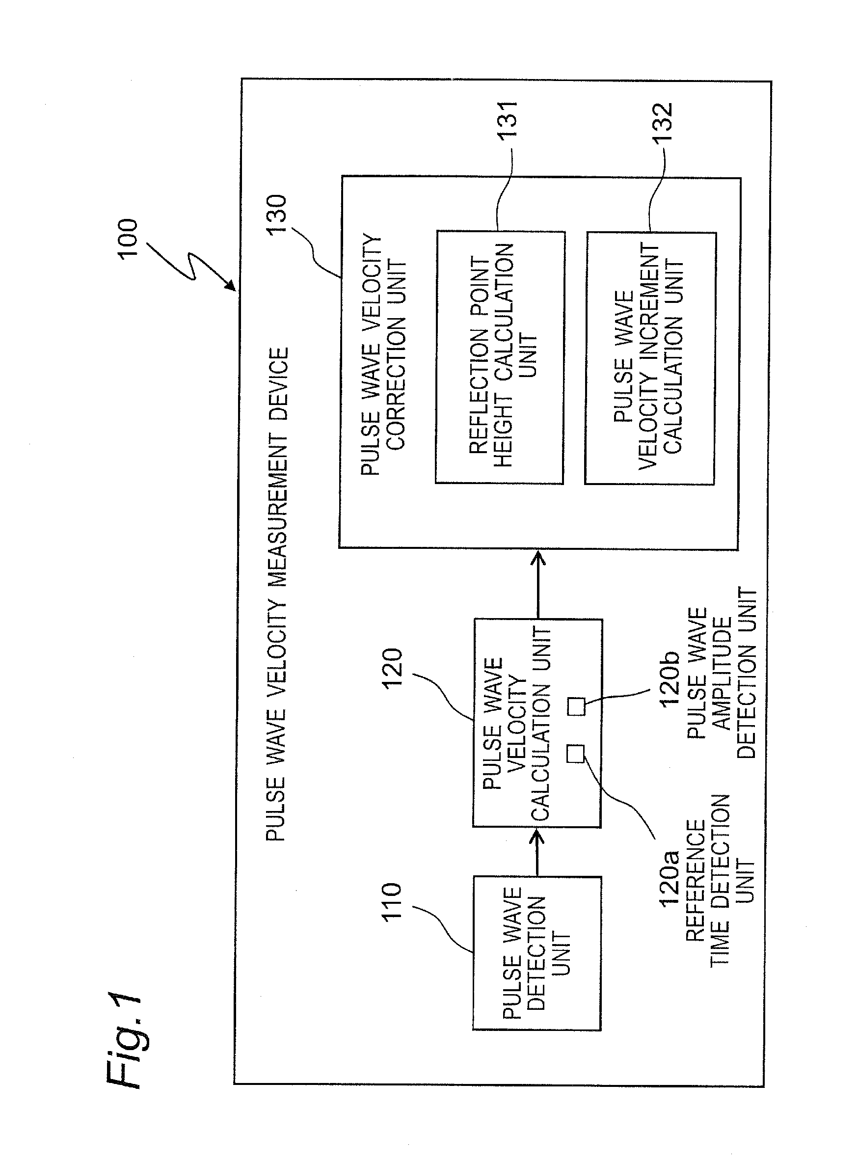
[0064]FIG. 1 shows a block diagram for a pulse wave velocity measurement device 100 in accordance with a first embodiment of the invention.

[0065]Main components of the pulse wave velocity measurement device 100 in accordance with the first embodiment are a pulse wave detection unit 110, a pulse wave velocity calculation unit 120, and a pulse wave velocity correction unit 130.

[0066]The pulse wave detection unit 110 detects pulse wave at one site in a human body. There are various methods by which the pulse wave detection unit 110 detects the pulse wave. For instance, there are photoplethysmography in which a degree of reflection or absorption of infrared red light outputted from a light emitting device according to a quantity of blood in a blood vessel is measured by a light receiving device, a pressure pulse wave method in which a change in pressure of blood in a blood vessel against the blood vessel is extracted as electric signals, and the like.

[0067]Especially severe limitations ...

second embodiment

[0121]FIG. 8 shows a block diagram for a pulse wave velocity measurement device 200 in accordance with a second embodiment of the invention. The pulse wave velocity measurement device 200 in accordance with the second embodiment has the same configuration as the pulse wave velocity measurement device 100 in accordance with the first embodiment has, except for a measurement position detection unit 133.

[0122]The pulse wave velocity measurement device 200 in accordance with the second embodiment has the pulse wave detection unit 110, the pulse wave velocity calculation unit 120, and the pulse wave velocity correction unit 130.

[0123]The pulse wave velocity correction unit 130 is composed of the measurement position detection unit 133, the reflection point height calculation unit 131, and the pulse wave velocity increment calculation unit 132.

[0124]The measurement position detection unit 133 detects a measurement position of a measured person. A change in the measurement position involve...


PUM


Abstract

A pulse wave velocity measurement device comprises a pulse wave detection unit (110) for detecting a pulse wave in a living body, a pulse wave velocity calculation unit (120) for calculating a pulse wave velocity on basis of the pulse wave detected by the pulse wave detection unit (110), and a pulse wave velocity correction unit (130) for correcting the pulse wave velocity calculated by the pulse wave velocity calculation unit (120) so as to eliminate an increment in the pulse wave velocity that results from influence of hydrostatic pressures caused according to a position of the living body. Thus, the pulse wave velocity measurement device can be provided that are capable of accurate measurement of the pulse wave velocity without being influenced by the hydrostatic pressures caused according to the position of the living body.

Description

TECHNICAL FIELD[0001]The present invention relates to a pulse wave velocity measurement device and particularly to a pulse wave velocity measurement device, a pulse wave velocity measurement method, and a pulse wave velocity measurement program that are for measuring pulse waves of a living body and thereby calculating velocity at which the pulse waves are propagated.BACKGROUND ART[0002]It has been known that pulse waves have various important information for grasp on a state of a circulatory system of a living body. In particular, velocity and time for propagation of a pulse wave between two sites in a living body are living-body indices that have drawn attention from the medical work front because a possibility has been pointed out that a state such as arteriosclerosis may be grasped by the indices, and are called Pulse Wave Velocity (PWV) and Pulse Transit Time (PTT), respectively, or the like.[0003]In general, two measurement points are required for PWV. It is known, however, th...

Claims


Application Information

Patent Timeline
Patent Type & Authority Applications(United States)
IPC IPC(8): A61B5/024
CPCA61B5/021A61B5/02125A61B5/7239A61B2560/0261A61B5/0285A61B5/02225A61B5/0295A61B5/7203
Inventor HORI, ATSUSHI
Owner SHARP KK
Learn More