Floating Foundation for Mass Production

a technology of floating foundations and mass production, applied in the direction of floating buildings, motors, vessel superstructures, etc., can solve the problems of high bending moments, increased construction expenditure, and high constructive expenditure, and achieves easy pre-manufacture, low material expenditure, and easy construction

Inactive Publication Date: 2013-01-24
JAHNIG GMBH FELSSICHERUNG & ZAUNBAU
View PDF2 Cites 56 Cited by
  • Summary
  • Abstract
  • Description
  • Claims
  • Application Information

AI Technical Summary

Benefits of technology

[0015]The buoyant bodies are, for example, single-chamber or multi-chamber hollow bodies that are made of concrete or steel. Preferably, they are arranged within a space that is enclosed and bounded by the frame work of the annular support. This provides a certain impact protection with regard to light collisions with watercraft or submerged watercraft or other objects. Also, an additional safety with respect to average is provided should buoyant bodies become detached from the annular support. They will not completely separate from the annular support and therefore will also not lose their carrying function. This lowers the constructive expenditure.
[0023]By anchoring the tower at the annular support by means of a group of first tension spokes that ascend the tower toward the annular support and a second group of tension spokes that are attached above the annular support to the tower and brace it in downward direction, the structure has a basic elasticity by which the structure near-shore as well as in areas remote from the shore is in particular capable of withstanding loads that occur at high wind speeds and rough seas. Pulsating, rhythmically repeating, but also stochastic loads are absorbed and diverted without disruptive stress concentrations.
[0024]The advantages of the structure according to the invention lie not only in their constitution in the erected state but also in its ease of construction. It can be erected with minimal expenditure in a very short construction time, for example, in a drydock. The latter comprises a basin that is filled with water or emptied as needed and that enables access to the ocean. The annular support and the buoyant bodies can be premanufactured in total or in parts. The floating support is positioned at a proper height above the ground of the drydock, for example, on blocks or movable props. The preferably premanufactured tower is then positioned, for example, by means of a crane, centrally and vertically in the annular support. Is it then only necessary to attach the tension spokes which can be done with extremely minimal personnel and machine expenditure by producing a few screw connections. After completion of the straightforward and short building process, the temporary support of the annular support can be removed, the basin can be flooded, and the structure can be towed to its installation site. It is then anchored there and is ready to use. The annular support can be assembled form uniform lattice segments, uniform support walls and uniform buoyant bodies. The uniform elements can be preassembled in mass production and can be transported by road because of their manageable dimensions.

Problems solved by technology

When bending forces are acting on the radial steel beams of the structure, they cause high bending moments.
Even though in connection with this structure it is said that it is subjected to only minimal oscillations, a high constructive expenditure is required.
At the central base of the tower, stress concentrations result that may cause problems; but, at least, they will increase the construction expenditure.
The erection of such a floating foundation requires a high material expenditure

Method used


Image

  • Floating Foundation for Mass Production
  • Floating Foundation for Mass Production
  • Floating Foundation for Mass Production

Examples


Embodiment Construction

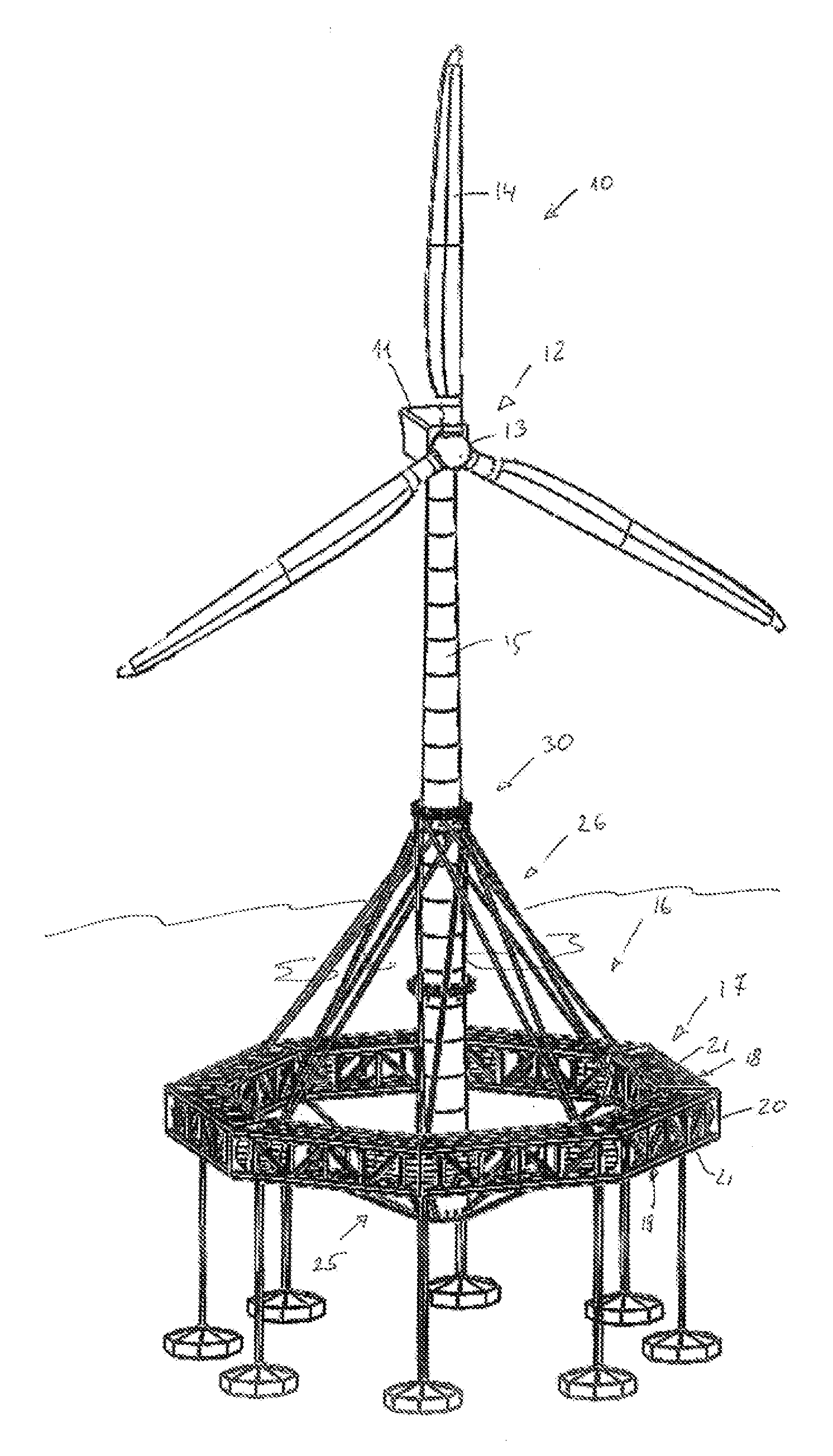
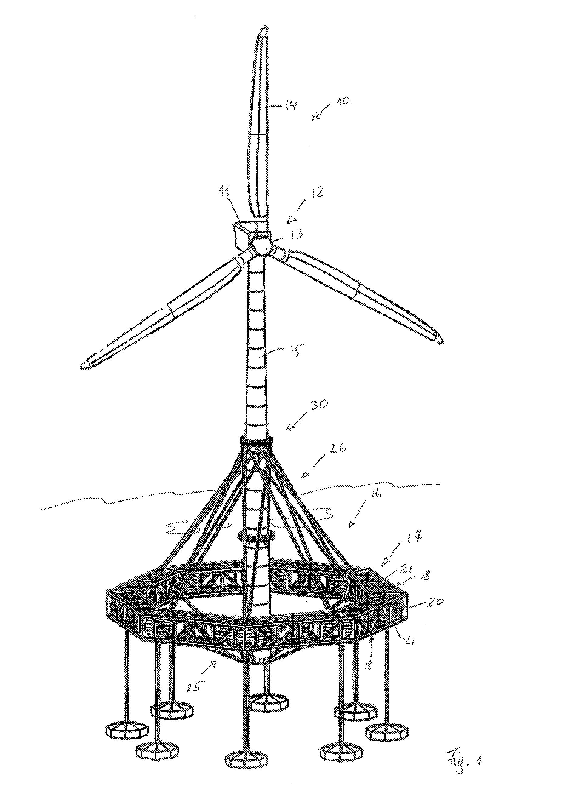
[0033]As an example of a structure 10 according to the invention, FIG. 1 illustrates a wind power plant. The latter comprises a nacelle 11 with rotor 12 comprising a hub 13 from which at least one, preferably however several, rotor blades 14 extend away. The hub 13 is supported rotatably about an approximately horizontal axis while the nacelle is arranged so as to be pivotable about a vertical axis on the upper end of the vertically arranged tower 15. Other structures can be erected according to the same principle in as much as they comprise a central tower that extends from below the water surface to at least somewhat above the latter and that supports a load thereat.

[0034]The tower 15 is supported by a floating foundation 16 wherein the lower part of the tower 15 is a functional component of the floating foundation 16. The floating foundation 16 moreover comprises an annular support 17 which, in the illustrated embodiment, is a lattice truss. It is of a circular ring-shape or, as ...


PUM

PropertyMeasurementUnit
tensionaaaaaaaaaa
angleaaaaaaaaaa
structureaaaaaaaaaa

Abstract

A floating structure has an annular support as an underwater support with a buoyant body. A tower penetrates the annular support centrally and is connected to the annular support at a location underneath the annular support by slantedly outwardly ascending tension spokes and at a location above the annular support by slantedly outwardly descending tension spokes. Anchors on the ocean floor are connected by tension elements with the annular support. The structure is built by the steps of supporting by auxiliary devices the annular support on a floor of a basin that can be flooded; positioning the tower at the center of the annular support in vertical position; attaching the tension spokes at the annular support and at the tower; flooding the basin; towing the structure to its desired final position; and lowering and anchoring the structure in a submerged floating position.

Description

BACKGROUND OF THE INVENTION[0001]The invention concerns a floating foundation and a method for its manufacture.[0002]In particular for erecting wind power plants, but also for anchoring other structures in the ocean, for example, marine navigation marks, drilling platforms and the like, numerous variants of floating foundations have been proposed. They are based on buoyant bodies which, in the immersed state, provide buoyance that is significantly greater than the weight of the structure and of the load to be carried wherein the buoyant bodies are anchored by cables or chains to the ocean floor in the submersed state.[0003]For example. GB 2 378 679 discloses such a floating foundation for a wind power plant. It is comprised of several buoyant bodies that are connected by means of radial steel beams to the tower. In plan view, the steel beams are arranged in crossing arrangement and are not connected to each other.[0004]When bending forces are acting on the radial steel beams of the ...

Claims


Application Information

Patent Timeline
Patent Type & Authority Applications(United States)
IPC IPC(8): B63B35/44B63B9/00F03D11/04
CPCB63B1/04Y10T29/49826B63B9/065B63B15/02B63B35/44F03D11/045B63B2001/044B63B2003/145B63B2009/067B63B2035/446B63B2241/08B63B2241/12F05B2240/93Y02E10/727B63B3/04B63B21/502B63B75/00B63B77/10F03D13/22F03D13/25Y02E10/72Y02P70/50
Inventor JAHNIG, JENSZACHARIAS, ALEXANDER
Owner JAHNIG GMBH FELSSICHERUNG & ZAUNBAU
Why Eureka
Try Eureka