
Bell column downtube, reactors utilizing same and related methods

a technology of bell column and downtube, which is applied in the field of reactors, can solve the problems of more difficult to convert resources into useable forms of energy, and inefficient extraction of oil from such sources in the past,

Inactive Publication Date: 2013-01-24
BATTELLE ENERGY ALLIANCE LLC
View PDF0 Cites 6 Cited by
  • Summary
  • Abstract
  • Description
  • Claims
  • Application Information

AI Technical Summary

Benefits of technology

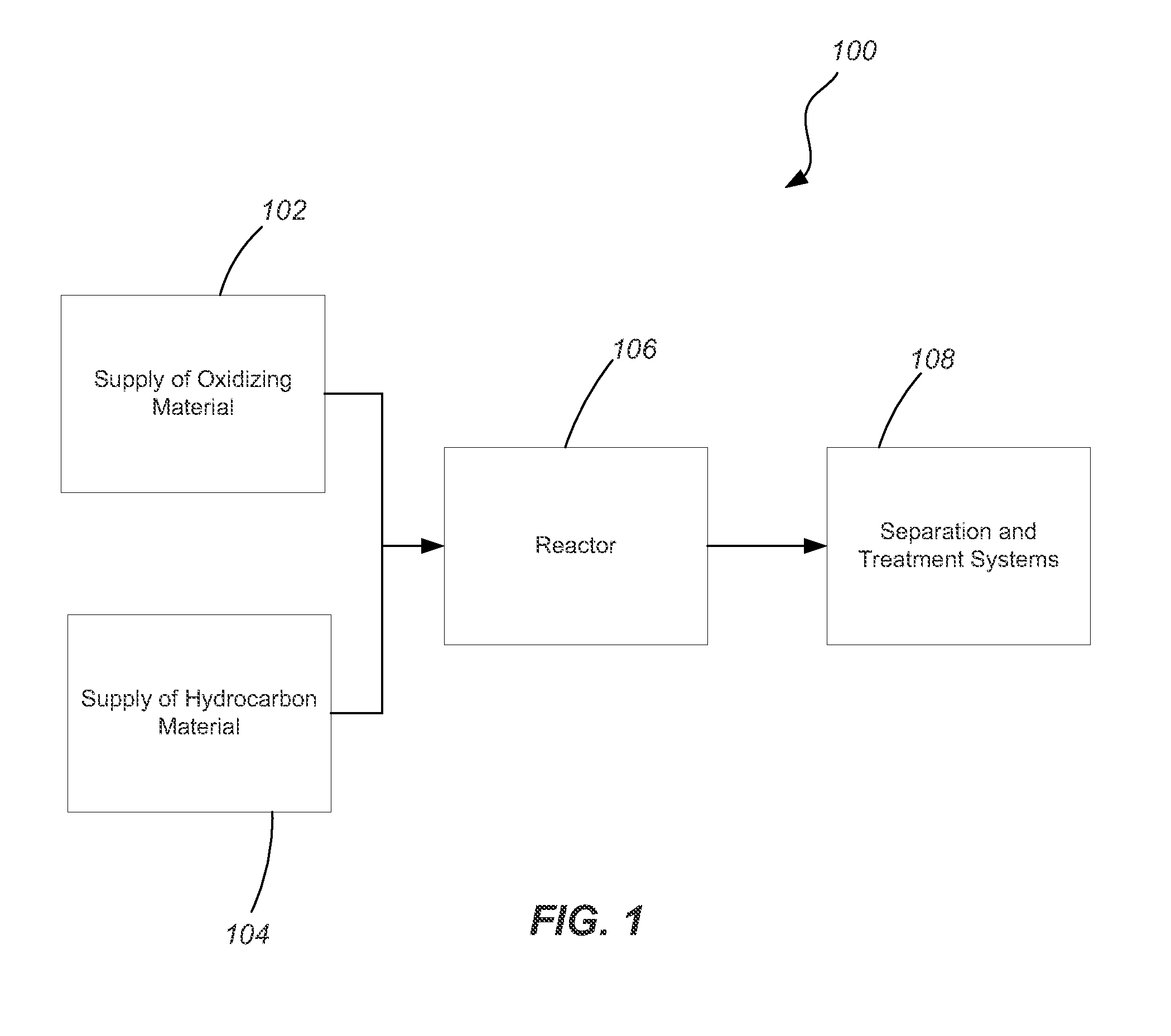
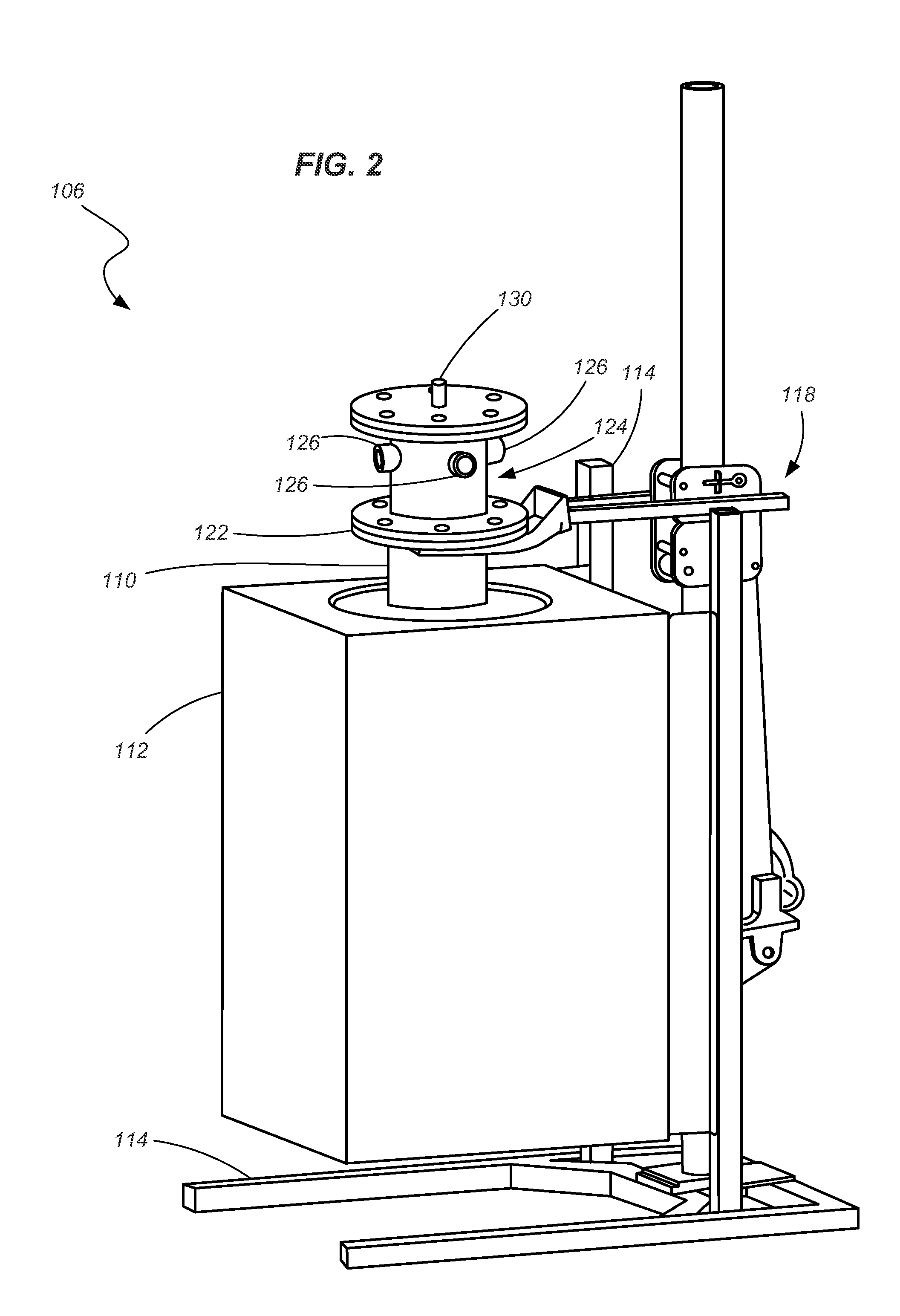
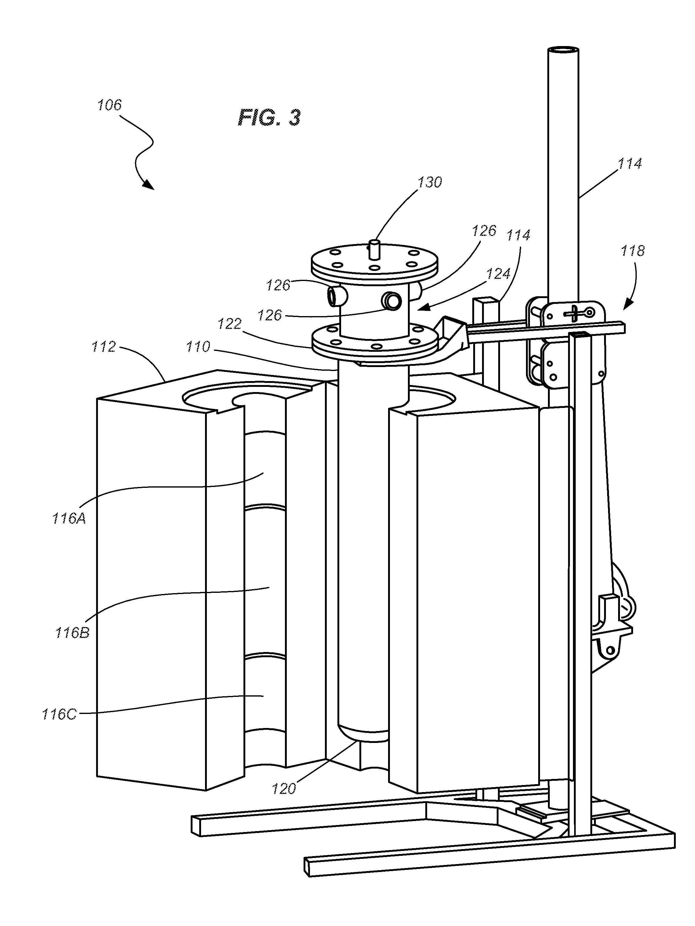
The present invention provides a reactor for producing gases, which includes a furnace and a crucible positioned for heating by the furnace. A downtube is disposed at least partially within the interior crucible along an axis and has a first end and a second end. The downtube has a plurality of holes formed therein enabling fluid flow through the downtube. A structure is coupled with the downtube and extends substantially across the interior volume of the crucible. The structure has a plurality of holes formed therein enabling fluid flow through the structure. The reactor can be used in a gas processing system and a method for controlling a reaction within the reactor is also provided. The technical effects of the invention include improved gas production efficiency, simplified reactor design, and improved gas processing system design.

Problems solved by technology

In some cases, these resources or reserves have been ignored because they are not as carbon rich as other available resources.
In other instances it is simply more difficult to convert the resource into a useable form of energy.
While technically feasible, extraction of oil from such sources in the past has conventionally been considered inefficient and ecologically unfriendly.
However, as those of ordinary skill in the art will recognize, all of these efforts are met with various obstacles, some economical, some political, and some scientific.

Method used


Image

  • Bell column downtube, reactors utilizing same and related methods
  • Bell column downtube, reactors utilizing same and related methods
  • Bell column downtube, reactors utilizing same and related methods

Examples


Embodiment Construction

[0024]Significant effort has been focused on energy conversion, energy efficiency, and the optimal use of resources in meeting the energy demands of mankind. The present disclosure describes reactors and that may be used in extracting an energy source (e.g., hydrogen or other gases) from a given material. Various components and methods associated with such reactors are also set forth herein. One embodiment of the present invention described herein includes an alkaline metal reactor that processes materials in a manner referred to as alkaline metal reforming (AMR). However, various aspects of the described inventions may be applicable to a spectrum of energy conversion.

[0025]One benefit of using an AMR process is that a wide range of feed materials may be reformed into a more useful energy source. Feed materials generally include an oxidizing material and some form of hydrocarbon, though straight carbon is also useable. In one embodiment, the hydrocarbon material may include a residu...


PUM

PropertyMeasurementUnit
temperatureaaaaaaaaaa
interior volumeaaaaaaaaaa

Abstract

Reactors for carrying out a chemical reaction, as well as related components, systems and methods are provided. In accordance with one embodiment, a reactor is provided that includes a furnace and a crucible positioned for heating by the furnace. A downtube is disposed at least partially within the interior crucible along an axis. At least one structure is coupled with the downtube and extends substantially across the cross-sectional area of the interior volume taken in a direction substantially perpendicular to the axis. A plurality of holes is formed in the structure enabling fluid flow therethrough. The structure coupled with the downtube may include a lower body portion and an upper body portion coupled with the lower body portion, wherein the plurality of holes is formed in the lower body portion adjacent to, and radially outward from, a periphery of the upper body portion.

Description

GOVERNMENT RIGHTS[0001]This Invention was made under a Cooperative Research and Development Agreement between Western Hydrogen and Battelle Energy Affiance, LLC under Contract No. DE-AC07-05ID14517, awarded by the U.S. Department of Energy. The U.S. Government has certain rights in the invention.TECHNICAL FIELD[0002]The present invention relates generally to reactors used in the production of gasses and, more particularly, components and methods used in reactors such as alkaline metal reactors.BACKGROUND[0003]Hydrocarbon based fuels (including petroleum products, natural gas, etc.) have been, and remain, a major source of global energy production. Projections of global oil reserves, the desire to provide more “green” or environmentally friendly energy, and many other issues have motivated individuals, companies and governments to research possible energy production alternatives. These research and development efforts have included the search for improved techniques, systems and meth...

Claims


Application Information

Patent Timeline
Patent Type & Authority Applications(United States)
IPC IPC(8): C10G1/04B01L3/00B01J19/00
CPCB01J19/2415C01B2203/1247B01J2219/00157C10J3/723C10J2300/0973C10J2300/0986C10J2300/1246C10J2300/1807C10J2300/0913B01J10/005C01B3/348C10J3/57C01B3/384C01B2203/0233C01B2203/04C01B2203/047C01B2203/0475C01B2203/06C01B2203/1005C01B2203/1041B01J4/002C10G1/083C10G2400/26
Inventor TURNER, TERRY D.BINGHAM, DENNIS N.BENEFIEL, BRADLEY C.KLINGLER, KERRY M.WILDING, BRUCE M.
Owner BATTELLE ENERGY ALLIANCE LLC
Learn More