Rotor Core For Motor

a rotor core and motor technology, applied in the direction of dynamo-electric machines, magnetic circuit rotating parts, magnetic circuit shapes/forms/construction, etc., can solve the problems of inability to achieve accurate power transmission and control, and achieve excellent rotor core moldability, evenness and accuracy, and no additional manufacturing costs and processes

Active Publication Date: 2013-01-24
LG INNOTEK CO LTD
View PDF10 Cites 24 Cited by
  • Summary
  • Abstract
  • Description
  • Claims
  • Application Information

AI Technical Summary

Benefits of technology

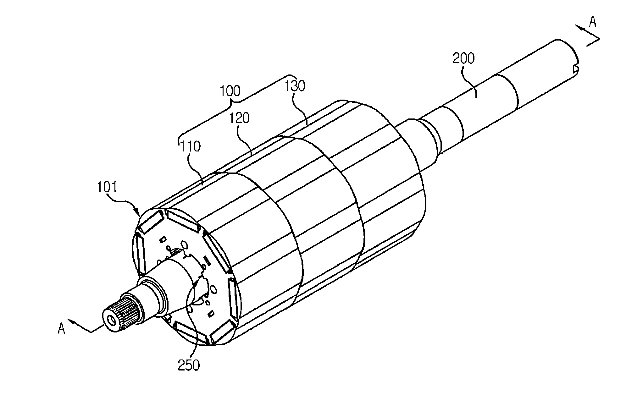
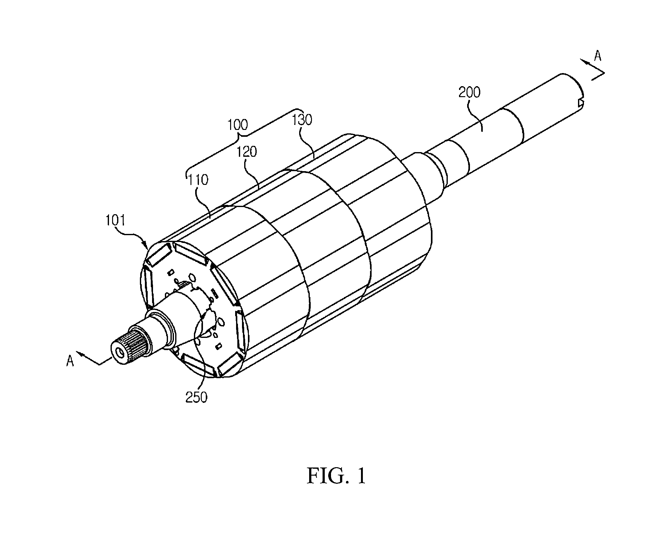
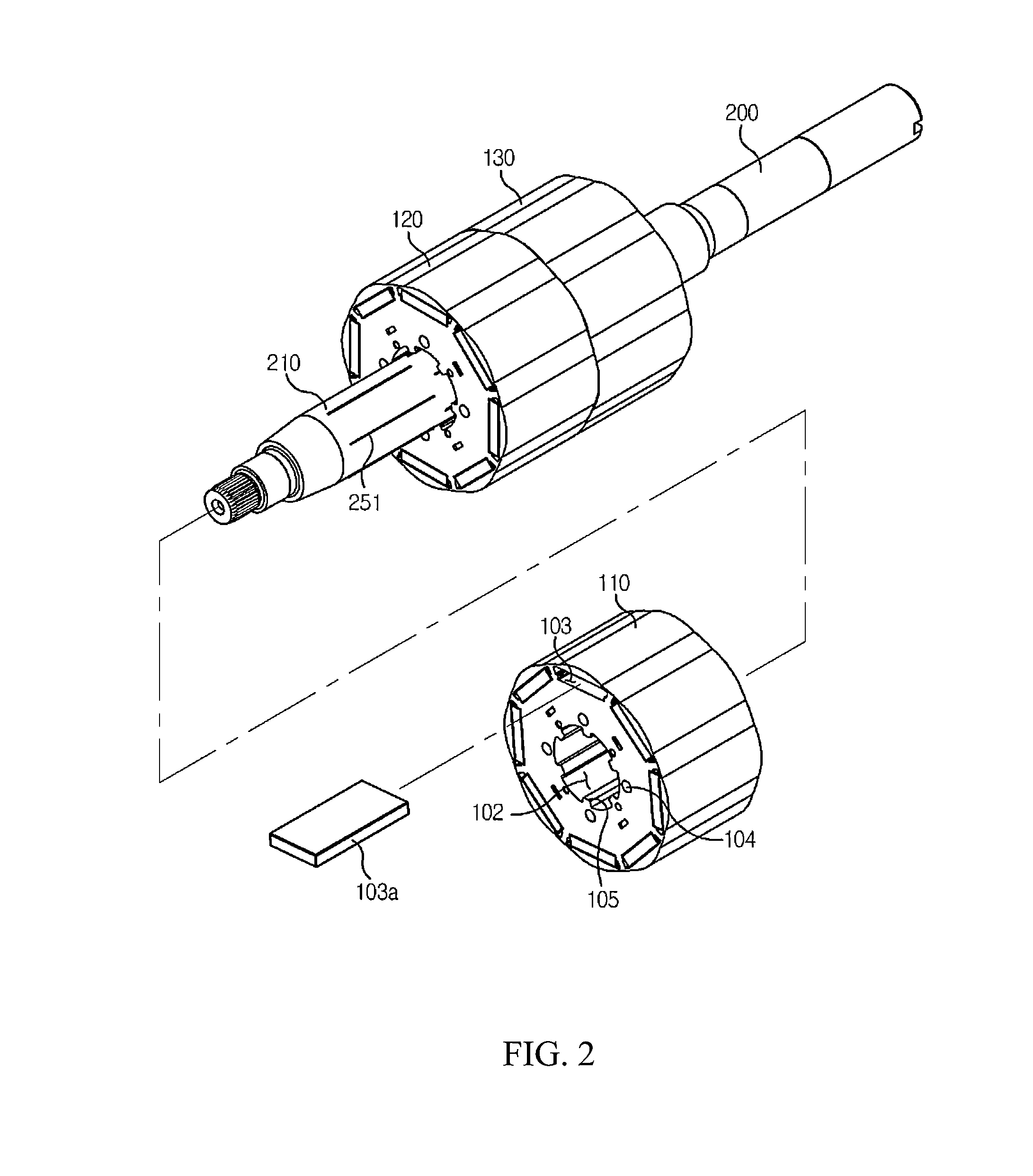
[0011]The present disclosure has been made to solve the foregoing problem(s) of the prior art, and therefore an object of certain embodiments of the present invention is to provide a rotor core of a motor configured to maintain a predetermined level of coherence between a shaft and the rotor core by improving a shaft surface and a shape of an inner diameter of the rotor core.
[0032]The rotor core of motor according to the present disclosure has an advantageous effect in that moldability, evenness and accuracy of rotor core of motor are excellent because a shape of an inner diameter of the stacked rotor core is determined by a shape determined by a mold shape of the rotor core.
[0033]Another advantage is that the a skived portion is formed only at a surface opposite to a contacted tooth portion after the shaft is press-fitted, and no interference is made with the skived portion in a case teeth of other rotor cores are press-fitted, thereby inhibiting the skived portion from being unnecessarily damaged in the course of being press-fitted.
[0034]Still another advantage is that there occur no additional manufacturing costs and processes, because it is sufficient to change a shape of a mold used in a punching process used in the manufacturing of the conventional rotor core.

Problems solved by technology

However, in case of sequential press-fitting of rotor cores, the skived surface of the shaft may be damaged in the press-fitting process of a first rotor core module, a sufficient interference cannot be reacted on second and third rotor core modules as calculated in design, and coherence between the rotor core and the shaft is not sufficiently formed to cause the shaft and the core to idle during rotation of rotor, whereby accurate power transmission and control cannot be realized.

Method used


Image

  • Rotor Core For Motor
  • Rotor Core For Motor
  • Rotor Core For Motor

Examples


Embodiment Construction

[0046]The disclosed embodiments and advantages thereof are best understood by referring to FIGS. 1-6 of the drawings, like numerals being used for like and corresponding parts of the various drawings. Other features and advantages of the disclosed embodiments will be or will become apparent to one of ordinary skill in the art upon examination of the following figures and detailed description. It is intended that all such additional features and advantages be included within the scope of the disclosed embodiments, and protected by the accompanying drawings. Further, the illustrated figures are only exemplary and not intended to assert or imply any limitation with regard to the environment, architecture, or process in which different embodiments may be implemented. Accordingly, the described aspect is intended to embrace all such alterations, modifications, and variations that fall within the scope and novel idea of the present invention.

[0047]Meanwhile, the terminology used herein is...


PUM


Abstract

Provided is a rotor core of a motor, the rotor core, the rotor core including: a thin disk-shaped rotor core member; a shaft hole penetratively formed in a center of the rotor core member; a shaft press-fitted into the shaft hole; a plurality of magnet insertion holes penetratively formed at a position near to a periphery of the rotor core member for inserted coupling by a magnet; a plurality of teeth protrusively formed at an inner circumferential surface of the shaft hole, and a skived portion protrusively formed at a position corresponding to the plurality of teeth of the shaft, wherein the rotor core members are stacked each at a predetermined height, and the shaft is press-fitted into the shaft hole.

Description

CROSS-REFERENCE TO RELATED APPLICATIONS[0001]This application claims the benefit under 35 U.S.C. §119 of Korean Patent Application Nos. 10-2011-0072977, filed Jul. 22, 2011 and 10-2011-0079464, filed Aug. 10, 2011, which are hereby incorporated by reference in their entirety.BACKGROUND[0002]1. Field of the Disclosure[0003]The present disclosure relates to a rotor core for motor.[0004]2. Discussion of the Related Art[0005]This section provides background information related to the present disclosure which is not necessarily prior art.[0006]In general, a rotor of a BLDC (Brushless direct current) motor is formed by press-fitting a shaft into a rotor core formed by being stacked with thin rotor core members. At this time, a surface of the shaft is performed with a surface treatment using mechanical means, e.g., knurling or skiving to inhibit the stacked rotor core and the shaft from idling. Once the shaft is surface-treated with knurling or skiving, press-fit force, pull-off force and ...

Claims


Application Information

Patent Timeline
Patent Type & Authority Applications(United States)
IPC IPC(8): H02K1/27
CPCH02K1/276H02K2201/06H02K1/28H02K2213/03
Inventor RYU, WOONGSEONKIM, HYUNSEOP
Owner LG INNOTEK CO LTD
Why Eureka
Try Eureka