Measuring Optical System, And Color Luminance Meter and Colorimeter using the Same

Active Publication Date: 2013-01-24
KONICA MINOLTA OPTICS
View PDF7 Cites 43 Cited by
  • Summary
  • Abstract
  • Description
  • Claims
  • Application Information

AI Technical Summary

Benefits of technology

[0011]In a measuring optical system of the present invention, and a color luminance meter and a colorimeter of the present invention each using the measuring optical system, measuring light is split into two or more, and, before each split light is received by a respective one of two or more light-receiving sensors through a respective one of two or more interference filters, it is introduced into the interference filter through a respective one of two or more collecting lens groups each formed as a substantially bilateral telecentric system. Each of the i

Problems solved by technology

However, each of the color filters is configured by laminating a plurality of optical absorption filters in such a manner as to transmit incident light at a transmittance corresponding to a respective one of a plurality of desired spectral characteristics such as the tristimulus values X, Y, Z, so that there is a problem that it is impossible to design a filter having a characteristic with transmittance peaks in two wavelength bands, as illustrated,

Method used


Image

  • Measuring Optical System, And Color Luminance Meter and Colorimeter using the Same
  • Measuring Optical System, And Color Luminance Meter and Colorimeter using the Same
  • Measuring Optical System, And Color Luminance Meter and Colorimeter using the Same

Examples


embodiment 1

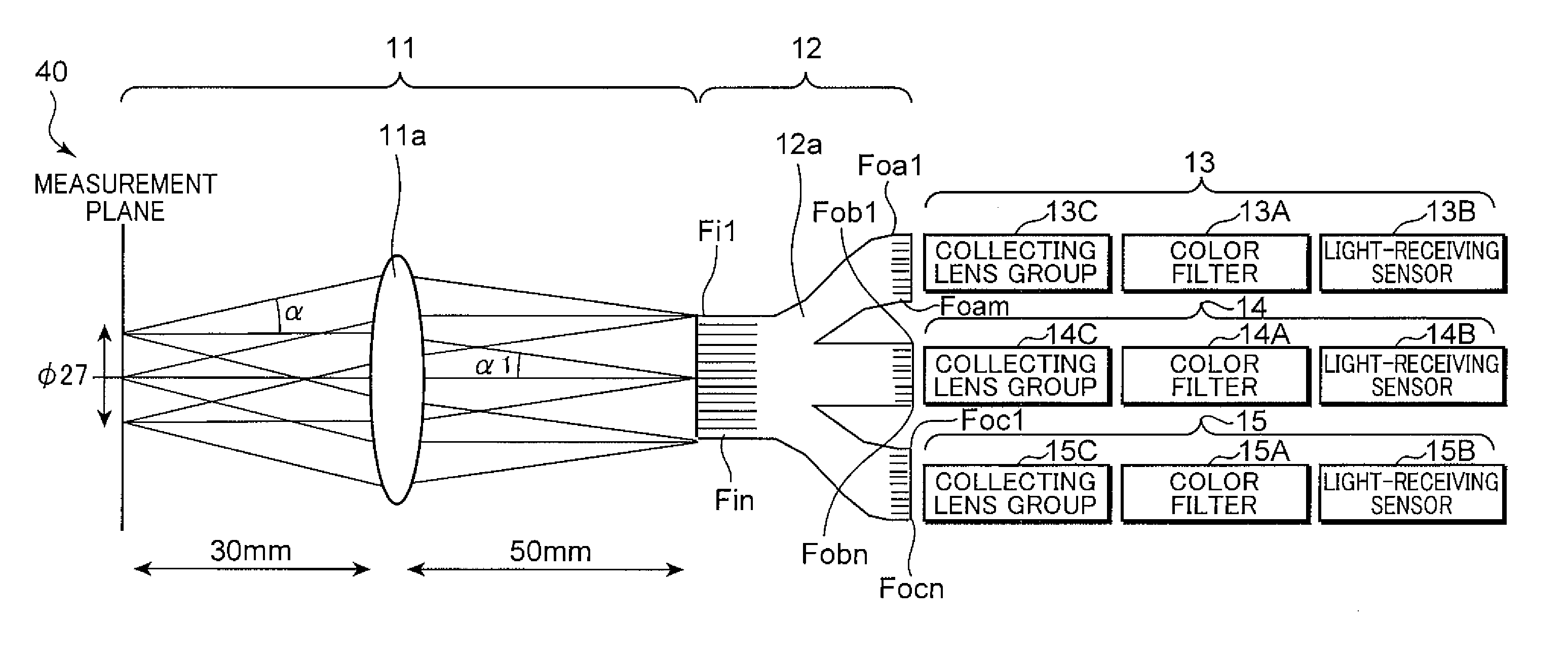
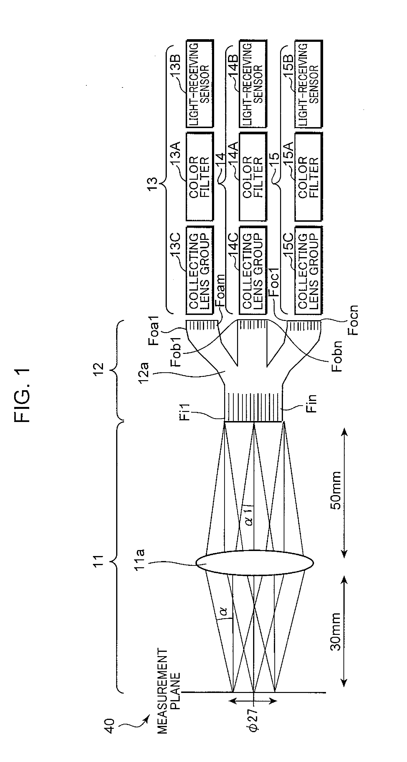
[0064]An embodiment will be described below. FIG. 1 is a diagram illustrating an internal configuration (measuring optical system) of a measuring probe 40 according this embodiment. This measuring probe 40 is used as the measuring probe 4 of the color luminance meter illustrated in FIG. 15 or of the colorimeter illustrated in FIG. 16. As one example of a measurement method, a color luminance meter is configured by equipping it with the measuring probe 40 disposed opposed to a display screen 3 of a liquid crystal monitor 2, and a main meter unit 5 for obtaining a color and a luminance based on an output of the measuring probe 40, in the same manner as that mentioned above in connection with FIG. 14. As another example of the measurement method, a colorimeter is configured by equipping it with a measuring light illumination unit for emitting measuring light to a measuring object, a measuring probe 40 for measuring reflected light which is the measuring light reflected from the measuri...


PUM


Abstract

In a measuring probe (40) according to the present invention, measuring light is split into a two or more through a split optical system (12), and, when each split light is received by a light-receiving sensor (13B, 13B, 15B) through an interference filter (13A, 14A, 15A) serving as a color filter, the split light is introduced into the interference filter (13A, 14A, 15A) through a collecting lens group (123C, 14C, 15C) formed as a substantially bilateral telecentric system. The interference filter (13A, 14A, 15A) is formed to obtain a transmittance characteristic corresponding to a measurement parameter, depending on a condition of an intensity distribution with respect to incidents angles of light incident on the interference filter (13A, 14A, 15A). Thus, the measuring probe (40) according to the present invention can reduce an influence of a deviation in the transmittance characteristic due to incident angles, even using the interference filter (13A, 14A, 15A).

Description

TECHNICAL FIELD[0001]The present invention relates to a measuring optical system for use, for example, in a color luminance meter for receiving light emitted from a light source such as a liquid crystal monitor and a lamp to measure a luminance (Lv) and a chromaticity (x, y) of the light source or a colorimeter for receiving light emitted onto and then reflected by a measuring object to measure a reflectance and a chromaticity (Lab, etc.) of the measuring object, and a color luminance meter and a colorimeter each using the measuring optical system.BACKGROUND ART[0002]A color luminance meter for measuring a luminance (Lv) and a chromaticity (x, y) of a liquid crystal monitor is configured by equipping it, for example, with a measuring probe disposed opposed to a display screen of the liquid crystal monitor, and a main meter unit. The measuring probe is operable to measure, for example, tristimulus values of X, Y, Z color-matching functions defined by the CIE (International Commission...

Claims


Application Information

Patent Timeline
IPC IPC(8): G01N21/25
CPCG01J3/02G01J3/0208G01J3/0218G01J3/024G01J3/506G01J3/51G02F1/1309G02B6/04G02B6/2804G02B27/10G02B27/1006G02F2001/136254G02F2203/69G01J3/513G02F1/136254
Inventor TSURUTANI, KATSUTOSHI
Owner KONICA MINOLTA OPTICS
Why Eureka
Try Eureka