Hydraulic system for actuating at least one shifting element of a transmission
- Summary
- Abstract
- Description
- Claims
- Application Information
AI Technical Summary
Benefits of technology
Problems solved by technology
Method used
Image

Examples
Embodiment Construction
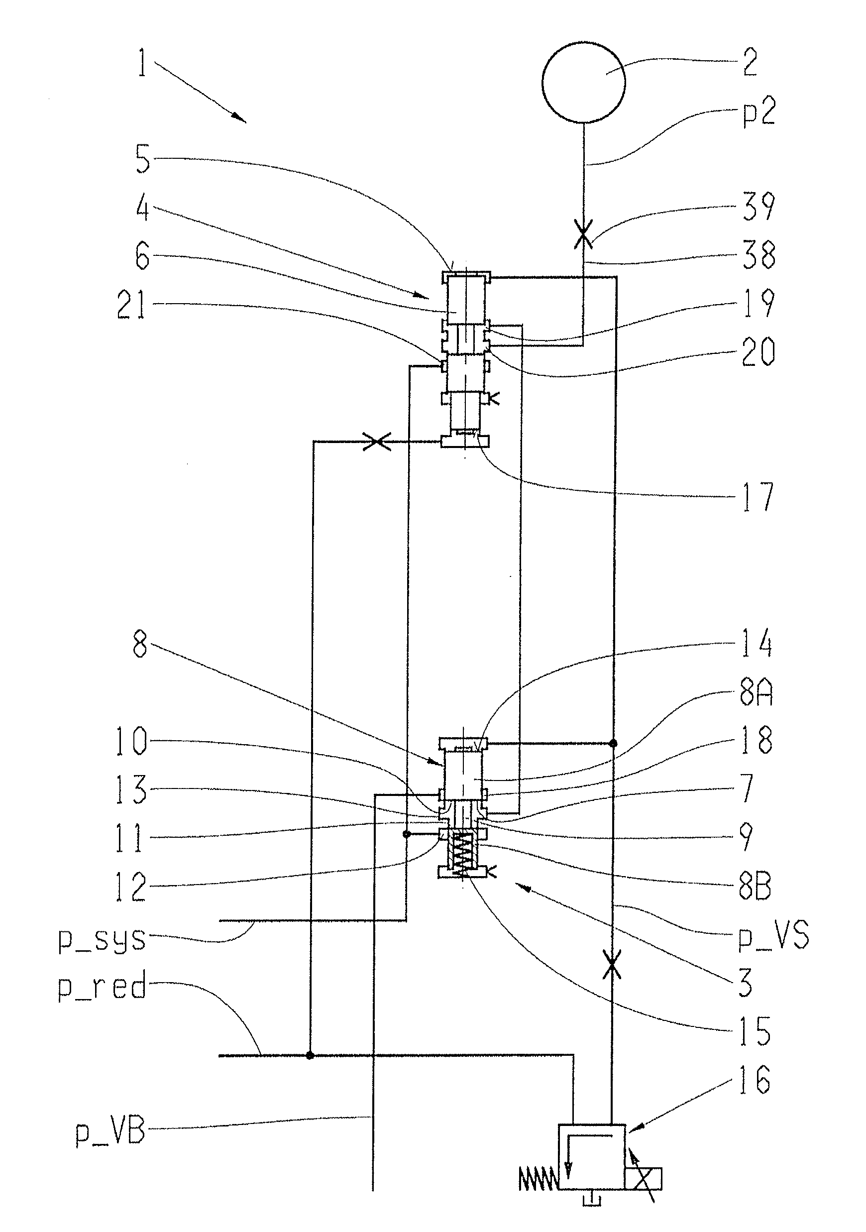
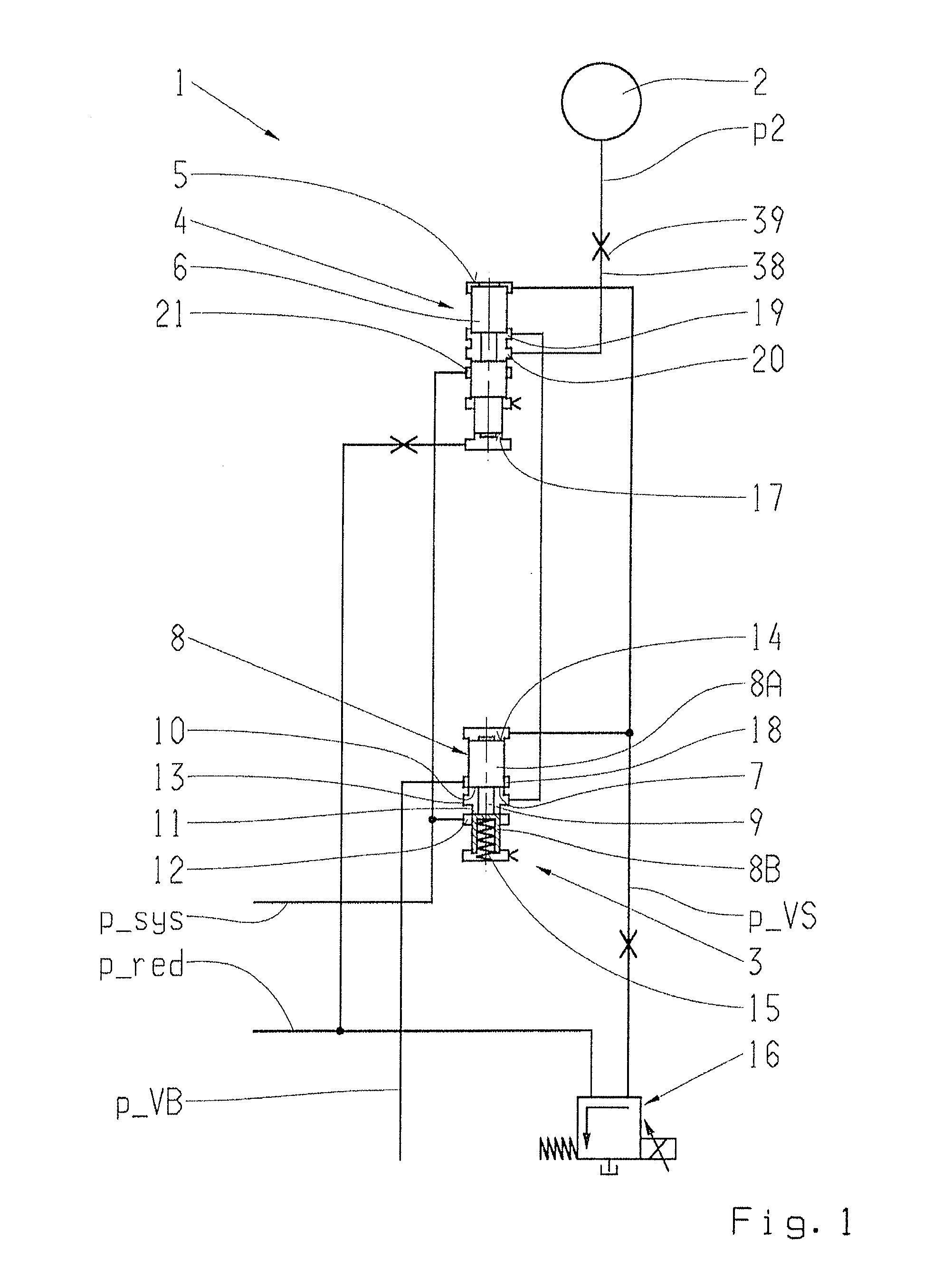
[0034]FIG. 1 shows a part of a first example embodiment of a hydraulic system 1 for actuating a shifting element 2 of the transmission device, wherein the present shifting element 2 is a friction clutch of the transmission device that can be hydraulically actuated. Depending on an actuating pressure p2 that can be applied to the shifting element 2, a transfer capability of the shifting element 2 can be varied between a value equal to zero and a maximum value.
[0035]The actuating pressure p2 of the shifting element 2 can be adjusted via a regulating valve device 3 that can be preset, and a shifting valve device 4 that can also be preset and is in effective connection thereto. Here, the actuating pressure p2 of the shifting element 2 can be regulated within a defined pilot pressure range via the regulating valve device 3, and when in a first shift state of the shifting valve device 4, represented in FIG. 1. Above a pilot pressure value present at a first effective surface 5 of a shifti...
PUM
 Abstract
Description
Claims
Application Information
 - R&D
- Intellectual Property
- Life Sciences
- Materials
- Tech Scout
- Unparalleled Data Quality
- Higher Quality Content
- 60% Fewer Hallucinations
Browse by: Latest US Patents, China's latest patents, Technical Efficacy Thesaurus, Application Domain, Technology Topic, Popular Technical Reports.
© 2025 PatSnap. All rights reserved.Legal|Privacy policy|Modern Slavery Act Transparency Statement|Sitemap|About US| Contact US: help@patsnap.com