Injection Moulding Plastic Components with a Slit

a technology of injection moulding and plastic components, which is applied in the field of injection moulding plastic components with a slit, can solve the problems of not producing an acceptable seal in the dispensing valve, the relative high rate of temperature drop, etc., and achieve the effect of enhancing the sealing integrity of the valve and enhancing the sealing integrity

Active Publication Date: 2013-01-31
CARBONITE CORP
View PDF8 Cites 16 Cited by
  • Summary
  • Abstract
  • Description
  • Claims
  • Application Information

AI Technical Summary

Benefits of technology

[0014]As mentioned above, the slit forms a seal to viscous liquids but not to air and the sealing integrity may be enhanced if the two first portions of the internal surface of the mould cavity are connected together by two third portions of the internal surface and the two second portions of the external surface of the mould member are connected together by two fourth portions of the external surface, whereby when the external apex is spaced from the internal apex by the predetermined distance the first and second portions are spaced apart by a first distance and the third and fourth portions are spaced apart by a second distance, the second distance being at least 10% and preferably at least 20% greater than the first distance. Thus the valve made in accordance with this aspect of the invention will have two inclined valve plates which together define a slit and are integrally connected by two curved portions of greater thickness. When the moulded component is allowed to cool, the two portions of greater thickness will contract more than the two thinner valve plates and this greater contraction will result in the two valve plates being placed under tension parallel to the slit. This tension will tend to hold the slit closed and thus to enhance the sealing integrity of the valve.

Problems solved by technology

The reason for this is not fully understood but it is believed to be due to the relatively rapid cooling that occurs due to the narrowness of the gap and the resulting relatively high rate of temperature drop that occurs above the apex.
If the predetermined distance has a value below the range given, a slit or elongate hole is formed in the finished product but this would have an appreciable width which would not produce an acceptable seal in a dispensing valve.

Method used


Image

  • Injection Moulding Plastic Components with a Slit
  • Injection Moulding Plastic Components with a Slit
  • Injection Moulding Plastic Components with a Slit

Examples


Embodiment Construction

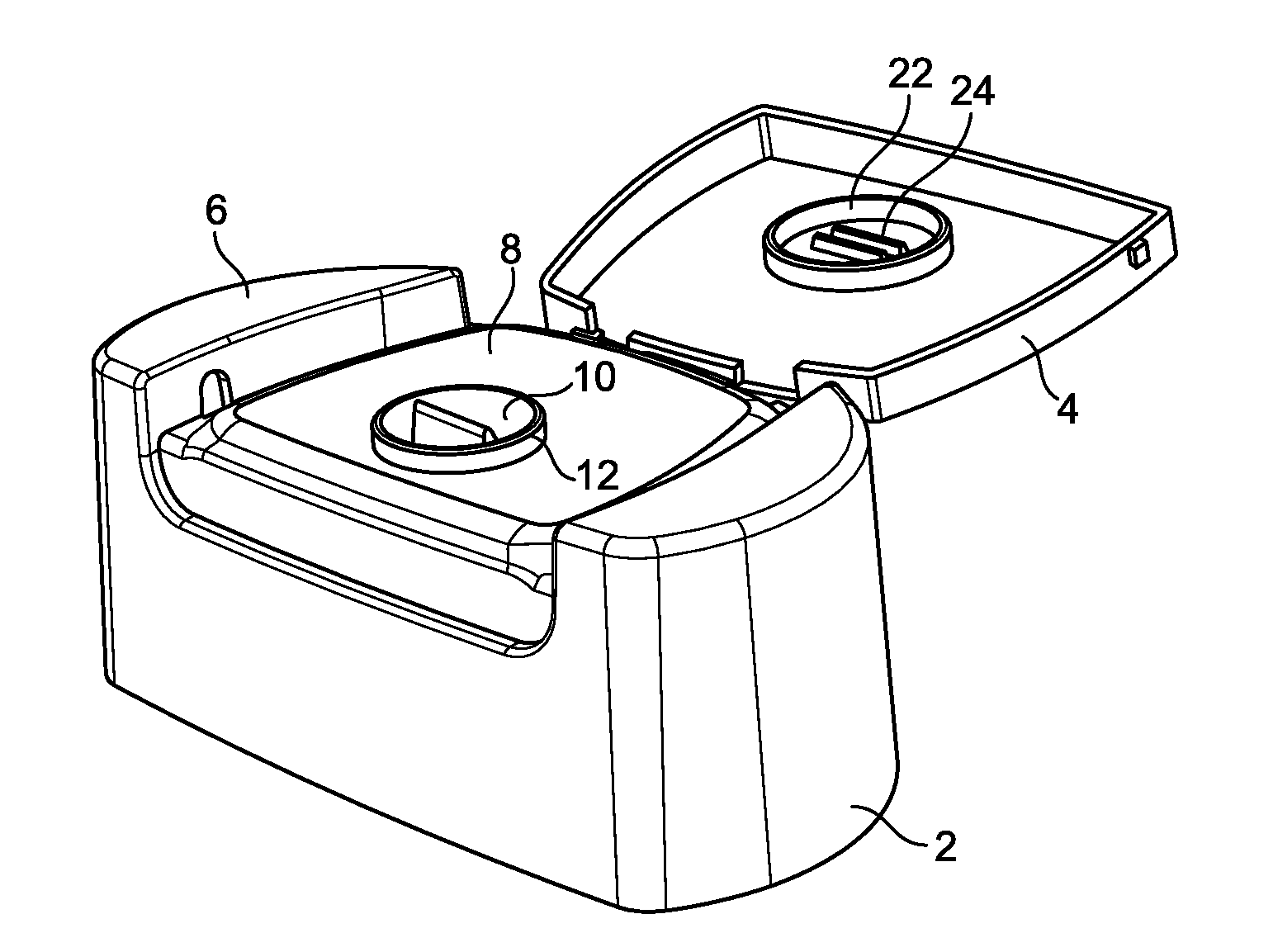
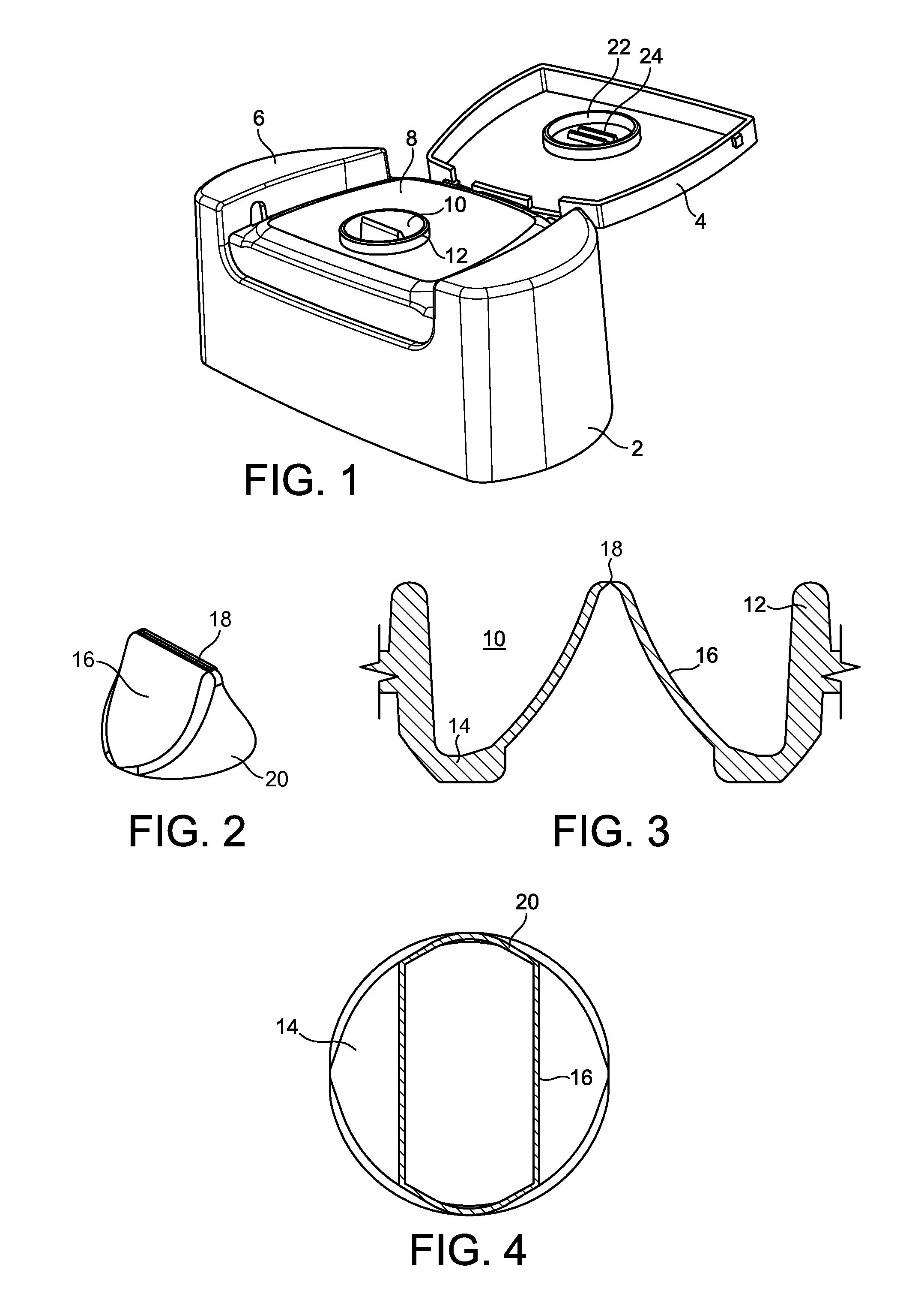
[0035]FIGS. 1 to 4 show a dispensing valve made in accordance with a first embodiment of the invention, which forms an integral part of the upper portion of a toiletries container, e.g. for shampoo, hair conditioner or the like. FIG. 1 shows the upper portion of the container, which, in use, is connected to the lower portion of the container, e.g. by welding or snap fitting. The upper portion of the container shown in FIG. 1 includes a cap 2, connected to one side of which by an integral hinge is a lid 4. The cap 2 is of rounded rectangular shape in plan view and at each end has a raised or upwardly extending portion 6. Between the two portions 6 is a recess, the lower surface 8 of which is substantially flat. Formed in the surface 8 is a recess or well 10 surrounded by an upstanding rim 12. At the bottom of the well 10 is a plate, referred to as a base plate 14, formed centrally in which is an aperture. Extending around and integral with the edge of the aperture is a dispensing val...


PUM

PropertyMeasurementUnit
distanceaaaaaaaaaa
distanceaaaaaaaaaa
distanceaaaaaaaaaa

Abstract

Method of injection moulding a plastics component includes providing a first mould member with a mould cavity, defined by an internal surface, and a second mould member with an external surface complementary to the mould cavity shape. Either the internal or external surface carry an elongate formation with an elongate apex. Then, the second mould member is advanced into the mould cavity such that the apex is spaced from the opposed one of the internal surface and the external surface by a predetermined distance and the internal surface of the first mould member and the external surface of the second mould member together define a mould space. Molten polyolefin material is then injected into the mould space to substantially fill it. The predetermined distance is so dimensioned that the polyolefin material does not completely fill the space between the apex and the opposed surface and the slit is thus formed.

Description

CROSS-REFERENCE TO RELATED APPLICATIONS[0001]This application is based on and claims priority from British Patent Application No. 1113097.8, filed on Jul. 28, 2011, the disclosure of which is incorporated herein in its entirety by reference.FIELD OF THE INVENTION[0002]The present invention relates to a method of injection moulding plastics components with a slit. There are many instances in which it is desired to injection mould a plastics component with a slit formed in it, that is to say a linear discontinuity at which the edges of the material substantially abut one another or are spaced apart by only a very small distance but are not connected together such that at least limited relative movement of the material on the two sides of the slit is possible.DESCRIPTION OF THE PRIOR ART[0003]One field of application of such components is fluid flow valves, particularly dispensing valves for dispensing viscous liquids or pasty materials, such as shower gel, hair conditioner, tomato ket...

Claims


Application Information

Patent Timeline
Patent Type & Authority Applications(United States)
IPC IPC(8): B29C45/16B65D47/00
CPCB29C45/0046B29C45/0081B29C45/34B29L2031/7506B29K2105/0094B65D47/2031B29C45/2628B29C2045/0049B29K2023/00B65D47/0804B29C45/00B65D47/08B65D47/20
Inventor SMITH, MATTHEW ERIC
Owner CARBONITE CORP
Why Eureka
Try Eureka