
Onboard Environment Recognition System

a recognition system and environment technology, applied in the field of onboard environment recognition system, can solve the problems of erroneous detection, low luminance in images, and inability to accurately recognize reflection regions having low luminance, etc., and achieve the effect of accurate recognition

Inactive Publication Date: 2013-01-31
HITACHI LTD
View PDF14 Cites 49 Cited by
  • Summary
  • Abstract
  • Description
  • Claims
  • Application Information

AI Technical Summary

Benefits of technology

The present invention aims to provide an onboard environment recognition system that can prevent errors caused by light from a vehicle's headlights in the surrounding environment. The system can accurately recognize the environment surrounding the vehicle by excluding the road surface reflection estimation image region that causes erroneous detection. This reduces the processing load and ensures accurate recognition.

Problems solved by technology

For an onboard camera that recognizes the environment surrounding a vehicle, not only a mirror reflection region having a high luminance on a road surface but also a region whose luminance is low but relatively high compared with the surroundings causes erroneous detection.
In particular, a rear camera, which shoots a video of a region not illuminated by the headlight of the vehicle in the nighttime, is required to detect a lane line or a vehicle in the low contrast video, so that a reflection region whose luminance is low but higher than that of the surrounding road surface causes erroneous detection.
Conventional techniques, such as those described above, can extract a reflection region having a high luminance but can hardly detect a reflection region having a low luminance in an image.
However, it is difficult for a monocular camera to shoot two images with different points of view at the same time.
In addition, an image recognition application is more susceptible to erroneous detection caused by a reflection region having a low luminance than that caused by a reflection region having a high luminance.
Thus, direct application of the principle disclosed in JP Patent Publication (Kokai) No. 2009-65360A can hardly solve the problem of erroneous detection.
Furthermore, the techniques disclosed in JP Patent Publication (Kokai) No. 11-203446A (1999) and JP Patent Publication (Kokai) No. 2009-65360A have a problem that, since the mirror reflection is recognized by image processing, the processing load is relatively high compared with the embodiments in which the image processing is applied only to simple extraction of a region having a high luminance, and the remaining road surface reflection regions are estimated by calculation.

Method used


Image

  • Onboard Environment Recognition System
  • Onboard Environment Recognition System
  • Onboard Environment Recognition System

Examples


embodiment 1

[0031]An onboard environment recognition system according to an embodiment 1 is integrated into an onboard camera on an automobile that displays, to the driver, an image of surroundings of the vehicle taken by a rear camera or a side camera for parking assistance.

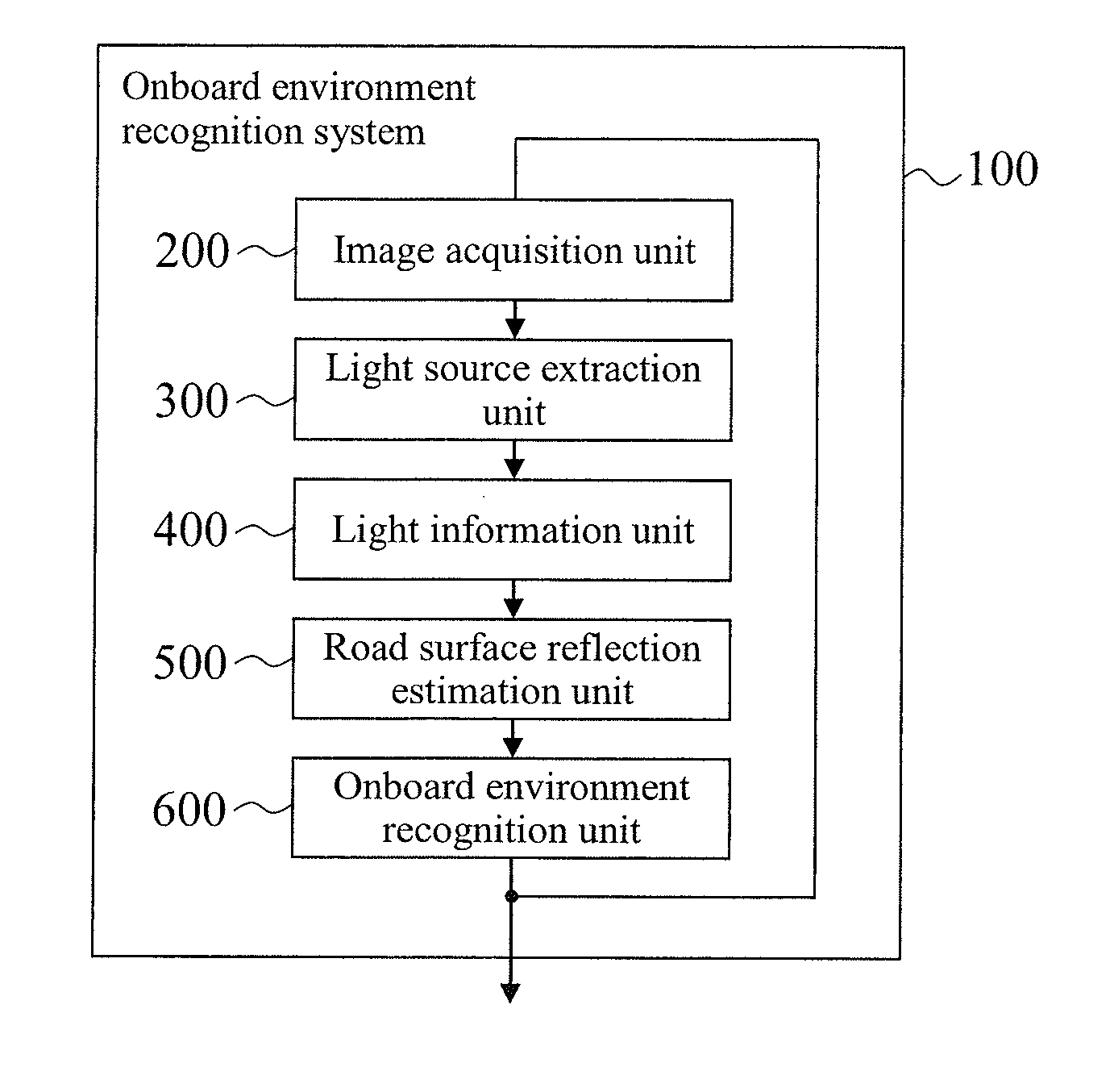
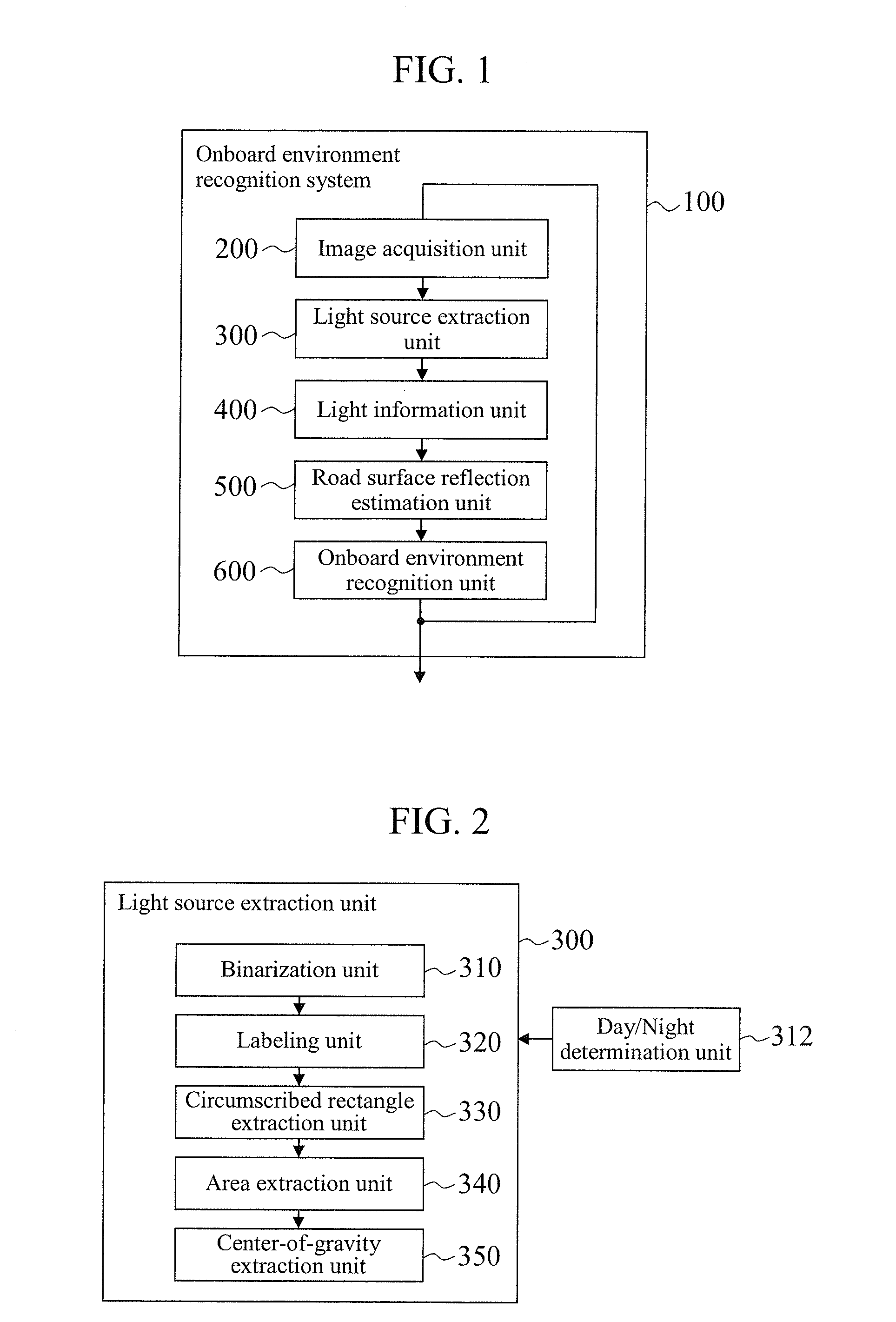
[0032]FIG. 1 is a diagram showing a configuration of the onboard environment recognition system according to this embodiment.

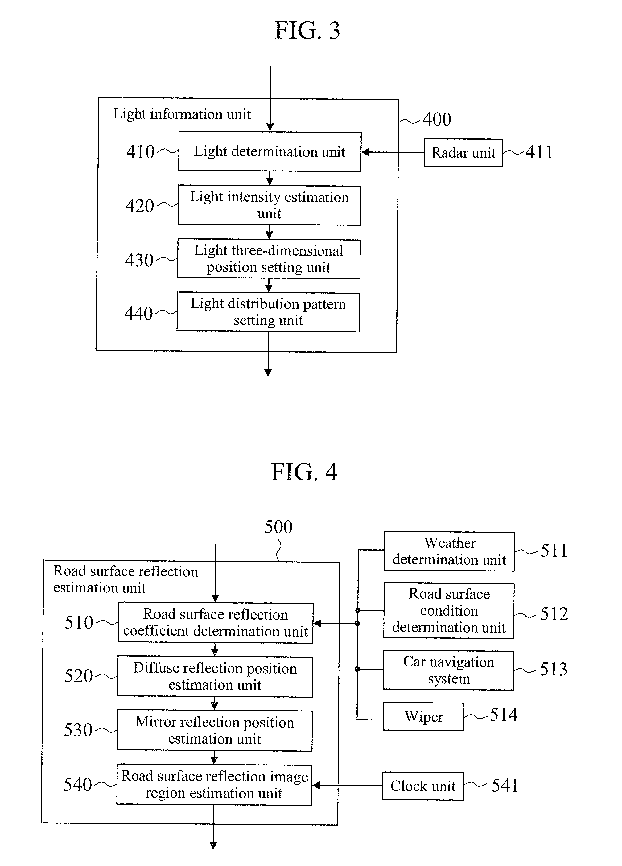
[0033]As shown in FIG. 1, an onboard environment recognition system 100 has an image acquisition unit 200, a light source extraction unit 300, a light information unit 400, a road surface reflection estimation unit 500 and an onboard environment recognition unit 600 as internal features of an ECU of an onboard camera.

[0034]The image acquisition unit 200 acquires an image of surroundings of the vehicle taken by a monocular camera, and the light source extraction unit 300 extracts a light source from the image acquired by the image acquisition unit 200. The light information unit 400 determines whether ...

embodiment 2

[0154]An embodiment 2 is characterized in that a road surface reflection estimation image region in the image caused by the evening or rising sun is estimated. The flow of the process of masking the road surface reflection estimation image region is basically the same as that in the embodiment 1, and therefore, only major differences from the embodiment 1 will be described in detail.

[0155]As shown in FIG. 14, the vehicle environment recognition system 100 has the day / night determination unit 312 that determines whether it is day or night and, based on the result of the determination by the day / night determination unit 312, selectively uses the light information unit 400 and the road surface reflection estimation unit 500 in the nighttime when the influence of the sunlight does not have to be taken into consideration or an evening sun-caused road surface reflection information unit 4000 and an evening sun-caused road surface reflection estimation unit 5000 in the daytime, such as mor...


PUM


Abstract

To provide an onboard environment recognition system capable of preventing, with a reduced processing load, erroneous recognition caused by light from a headlight of a vehicle in the surroundings. An onboard environment recognition system 100 has a light source extraction unit 300 that extracts a light source from an image, a light information unit 400 that extracts light whose light source causes erroneous detection in environment recognition based on the position of the light source in the image and estimates light information including information on the light intensity, the three-dimensional position and the light distribution pattern of the light, a road surface reflection estimation unit 500 that estimates, based on the light information, a road surface reflection estimation image region in the image in which the light is reflected on a road surface, and an onboard environment recognition unit 600 that recognizes the environment surrounding the vehicle based on the road surface reflection estimation image region.

Description

BACKGROUND OF THE INVENTION[0001]1. Field of the Invention[0002]The present invention relates to an onboard environment recognition system that recognizes the environment surrounding a vehicle based on an image taken by an onboard camera.[0003]2. Background Art[0004]In recent years, cameras have been developed that recognize the environment surrounding a vehicle, such as an automobile. The camera-based recognition technique tends to suffer from poor recognition in the nighttime when the visibility is low. In particular, a video taken by a rear camera tends to be darker and have less visibility because the road surface imaged by the rear camera cannot be illuminated by the head lamp of the vehicle, and the dark video needs an image processing. In addition, if there is a following vehicle, the video taken by the rear camera tends to lead to erroneous recognition because of a whiteout caused by the headlight of the following vehicle being extremely bright compared with the dark surroun...

Claims


Application Information

Patent Timeline
Patent Type & Authority Applications(United States)
IPC IPC(8): H04N7/18H04N13/00
CPCG06K9/00805G06K9/00798G06V20/588G06V20/58
Inventor TAKEMURA, MASAYUKIMURAMATSU, SHOJISHIMA, TAKESHISAKATA, MASAO
Owner HITACHI LTD
Learn More