
Transmission terminal and transmission method

a technology which is applied in the field of transmission terminal and transmission method, can solve the problems of data loss, delay, and communication for all transmission destinations, and achieve the effect of preventing the cpu load from becoming high

Inactive Publication Date: 2013-01-31
SONY CORP
View PDF2 Cites 4 Cited by
  • Summary
  • Abstract
  • Description
  • Claims
  • Application Information

AI Technical Summary

Benefits of technology

The patent technology aims to prevent decreased throughput at one location from affecting other transmission destinations while keeping the CPU load low.

Problems solved by technology

As a result, communication for all the transmission destinations, including those in which throughput is sufficient, may be delayed, and data may be lost.
However, since the number of threads to be generated increases, CPU load increases.
Furthermore, in a case where a transmission process is set to non-blocking, in the case where a transmission process is delayed, the transmission process is not blocked and an error occurs instantly.
However, a transmission destination in which throughput is sufficient also generates an error and this is unacceptable practically.

Method used

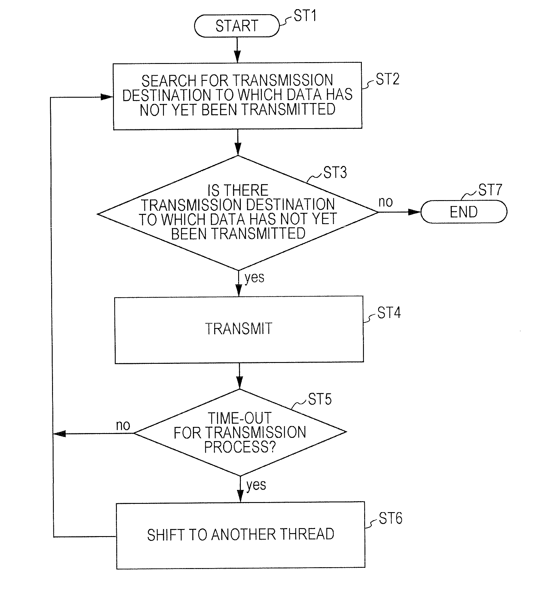

Image

  • Transmission terminal and transmission method
  • Transmission terminal and transmission method
  • Transmission terminal and transmission method

Examples


embodiment

1. Embodiment

[0031][Multiple Point Distribution System]

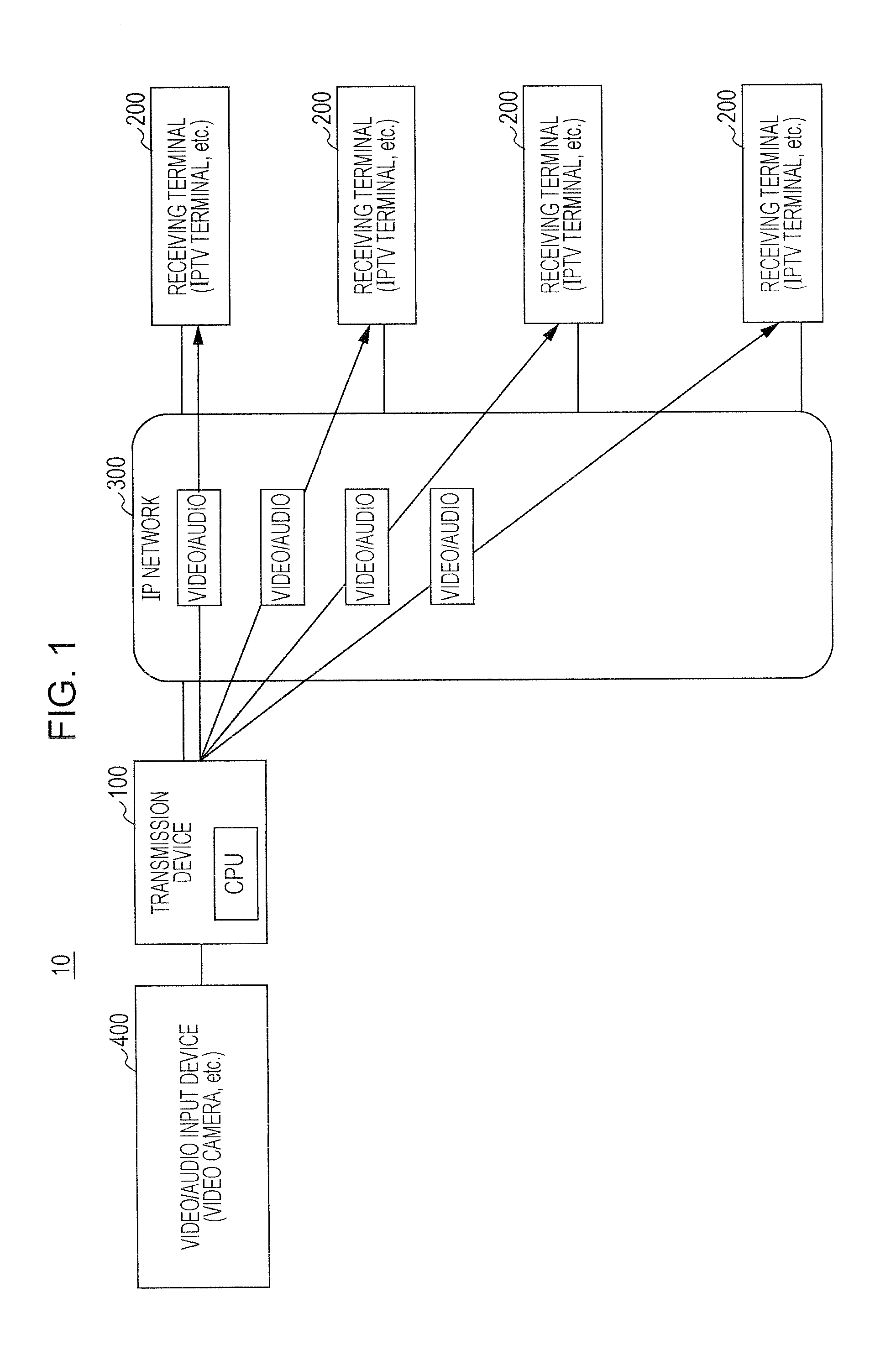
[0032]FIG. 1 illustrates an example of the configuration of a multiple point distribution system 10 according to an embodiment. The multiple point distribution system 10 is configured in such a way that a transmission terminal 100 and a plurality of receiving terminals 200 are connected to each other via an IP network 300. Here, the receiving terminals 200 form transmission destinations. Video audio input (video data, audio data) is supplied to the transmission terminal 100 from a video / audio input device 400, such as a video camera device. In the transmission terminal 100, a coding process and the like are performed on the video audio input, and a video stream including video data and audio data is generated. Then, in the transmission terminal 100, this video stream is sequentially transmitted to the plurality of receiving terminals 200 as transmission destinations for each data block by using TCP (Transmission Control Protocol...


PUM


Abstract

To realize a state in which a decrease in throughput at one place does not affect other transmission destinations while preventing CPU load from becoming high.The present technology can be applied to a multiple point distribution system that transmits a video stream to a plurality of transmission destinations by using a transport protocol having a congestion control mechanism, such as TCP. A transmission terminal transmits the video stream in the same thread (first thread) with respect to receiving terminals A and C in which throughput is sufficient, and transmits the video stream in another thread (second thread) with respect to a receiving terminal B in which throughput has decreased. As a result of adopting such a transmission method, a decrease in throughput for the receiving terminal B does not affect transmission to the receiving terminals A and C. Furthermore, transmission is not performed to the receiving terminals A, B, and C in mutually different threads, and an increase in the number of threads, thus, an increase in CPU load, can be suppressed.

Description

TECHNICAL FIELD[0001]The present technology relates to a transmission terminal and a transmission method. More particularly, the present technology relates to a transmission terminal that transmits the same data, such as a video stream, to a plurality of transmission destinations by using a transport protocol having a congestion control mechanism, such as TCP (Transmission Control Protocol), and relates to a transmission method for use therewith.BACKGROUND ART[0002]A system has been considered in which a transmission terminal transmits the same data, such as a video stream, to a plurality of transmission destinations by using a transport protocol, such as TCP. In a case where data is to he transmitted in the same thread to all the transmission destinations, if there is even just one transmission destination in which the transmission process is blocked, the transmission processes for all the other transmission destinations are made to wait until the block is released. As a result, co...

Claims


Application Information

Patent Timeline
Patent Type & Authority Applications(United States)
IPC IPC(8): H04L12/24
CPCH04L47/12H04L47/15H04L65/4076H04L29/06993H04N21/2402H04N21/64738H04L29/06115H04L65/80H04L69/28H04L69/163H04L65/611
Inventor MASUDA, YASUTO
Owner SONY CORP
Learn More