
1-Wire Communication Protocol and Interface Circuit for High Voltage Applications

Active Publication Date: 2013-01-31
IXYS CORP
View PDF2 Cites 4 Cited by
  • Summary
  • Abstract
  • Description
  • Claims
  • Application Information

AI Technical Summary

Benefits of technology

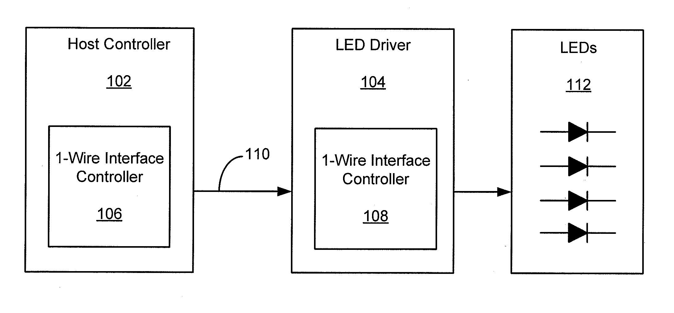
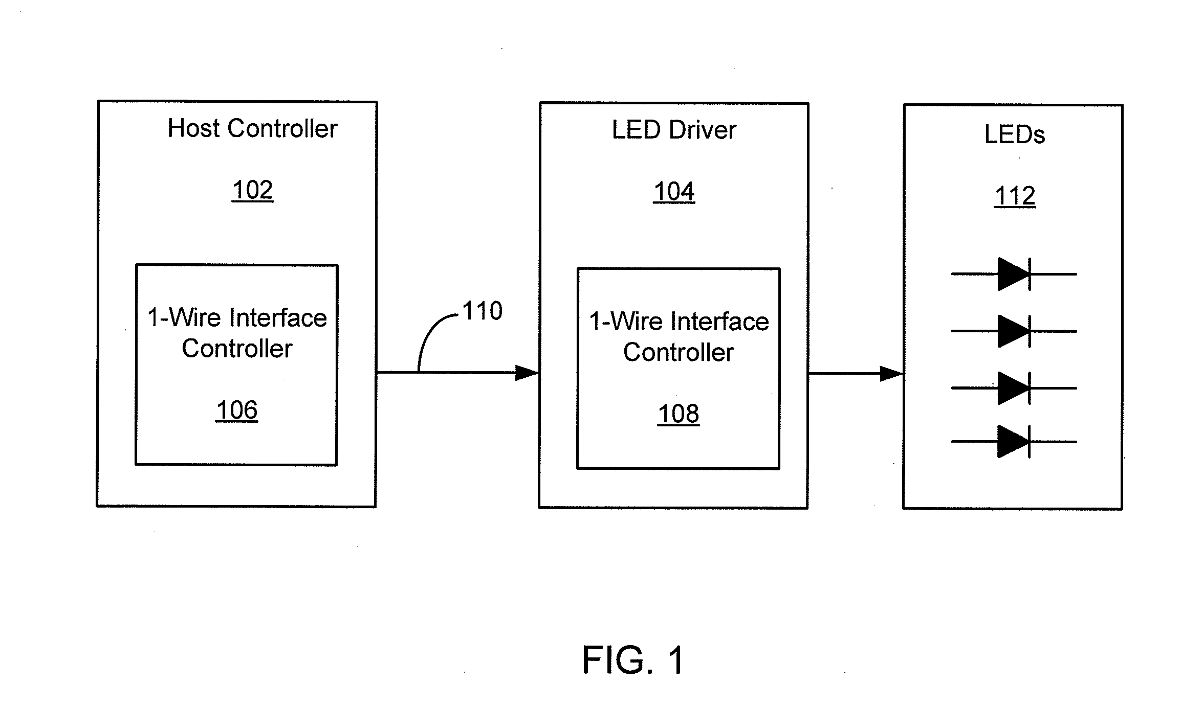
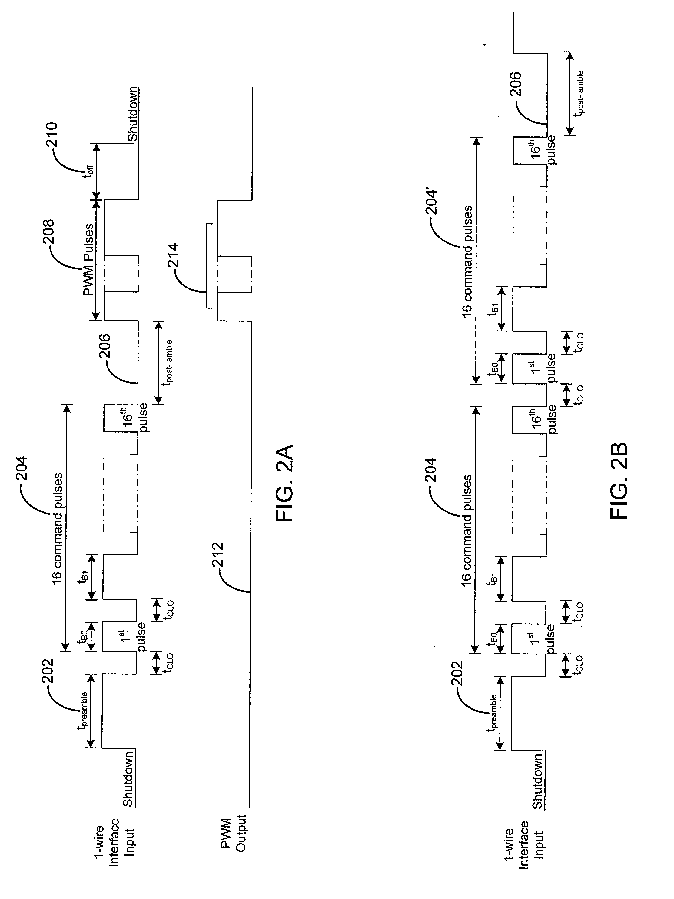
The invention provides a communication protocol and circuitry for communication between a host device and a driver device using a 1-wire interface. The protocol distinguishes between binary encoded command mode signals and analog encoded command mode signals by interpreting the length of pulses in the PWM signals. The same 1-wire interface is used for transmitting both programming commands and current setting commands, eliminating the need for additional wires or pins. The system includes a host controller, an LED driver device, and multiple LEDs, and the host controller sends binary encoded commands and analog encoded commands to the LED driver device for decoding by the driver device's 1-wire interface controller. The system can be used for high power applications and in different modes, such as a binary encoded command signal mode and an analog encoded command signal mode. The host sends each pulse in the PWM format as a pair of signals, and the driver circuit interprets the first pulse as a rising edge and the second pulse as a falling edge.

Problems solved by technology

The conventional 1-wire communication protocols cannot be used for dynamic communication of PWM signals to adjust the average current for driving the LEDs.
This adds to the complexity and manufacturing cost of the LED driver and host controller ICs.

Method used


Image

  • 1-Wire Communication Protocol and Interface Circuit for High Voltage Applications
  • 1-Wire Communication Protocol and Interface Circuit for High Voltage Applications
  • 1-Wire Communication Protocol and Interface Circuit for High Voltage Applications

Examples


Embodiment Construction

[0020]Reference will now be made in detail to several embodiments of the present invention, examples of which are illustrated in the accompanying figures. It is noted that wherever practicable similar or like reference numbers may be used in the figures and may indicate similar or like functionality. The figures depict embodiments of the present invention for purposes of illustration only. One skilled in the art will recognize from the following description that alternative embodiments of the structures and methods illustrated herein may be employed without departing from the principles of the invention described herein.

[0021]According to various embodiments of the present invention, a 1-wire communication protocol and interface circuitry for communication between a host device (e.g., a host controller) and a driver device (e.g., an LED driver) is disclosed. FIG. 1 illustrates an LED driver system controlled by a host controller 102 using a 1-wire communication protocol and interfac...


PUM


Abstract

A system for communicating with a host using control signals over a 1-wire interface is disclosed. The system includes a driver coupled to the host by the 1-wire interface. Control signals are transmitted from the host to the driver for decoding by the driver controller. The control signals are pulse width modulation format signals which are interpreted by the driver as binary encoded command mode signals or analog encoded command mode signals, depending upon when the signals are received in relation to a preamble pulse and a post-amble pulse.

Description

CROSS-REFERENCE TO RELATED APPLICATION[0001]This patent application is a continuation-in-part of U.S. patent application Ser. No. 12 / 696,987, filed Jan. 29, 2010, entitled “1-Wire Communication Protocol and Interface Circuit.”BACKGROUND OF THE INVENTION[0002]This invention relates to a communication protocol and interface circuit for communication between a host device and a driver device using a single wire interface, more commonly known as a 1-wire interface.[0003]Light-emitting diodes (LEDs) are being used increasingly in display devices and numerous lighting applications. For example, some liquid crystal display (LCD) devices use white LEDs as the backlight for the LCD display. These LEDs are typically driven by an LED driver that functions as a constant current device to supply a constant sink current fed through the LEDs to provide a constant luminescence. Alternatively they can function as an average current device to supply a switching pulse width modulation sink current fed...

Claims


Application Information

Patent Timeline
IPC IPC(8): H04L25/00H05B44/00
CPCH05B37/0254H04L25/4902H05B33/0818H03K7/08Y02B20/346H05B45/37H05B47/18Y02B20/30
Inventor NEYMAN, LEONID A.LIN, ALLAN MING-LUN
Owner IXYS CORP
Learn More