Non-Rigid Product Laying Apparatus

a non-rigid product and laying technology, applied in mechanical equipment, pipe laying and repair, pipe/joint/fitting, etc., can solve the problems of unworkable high center of gravity, heavy tower, and large traditional winch arrangement, etc., to achieve the effect of evenly spreading the load

Inactive Publication Date: 2013-01-31
J RAY MCCDERMOTT SA
View PDF16 Cites 1 Cited by
  • Summary
  • Abstract
  • Description
  • Claims
  • Application Information

AI Technical Summary

Benefits of technology

[0006]The present invention is directed to a dual long grip length clamp arrangement installed vertically into a tower in a similar manner to a J-lay trolley / clamp system. The invention differs from a J-lay arrangement in that two clamps are used and the clamps are configured for use with non-rigid product, i.e. they have a long grip length in order to spread the load evenly. Each clamp is mounted on a trolley and can travel vertically up or down. The upper clamp is arranged with a distance between it and the lower clamp such that the upper clamp can lower the product a suitable distance before the lower clamp grips the non-rigid product so as to create as close as possible continuous movement as practical.

Problems solved by technology

To construct a tensioner to take similar top tensions invariably leads to a very heavy tower with an unworkably high center of gravity.
This arrangement is used for very high tensions that would make a traditional winch arrangement too large to be viable.
Long tensioners are very heavy and also difficult to maintain a stiff grip surface.

Method used


Image

  • Non-Rigid Product Laying Apparatus
  • Non-Rigid Product Laying Apparatus
  • Non-Rigid Product Laying Apparatus

Examples


Embodiment Construction

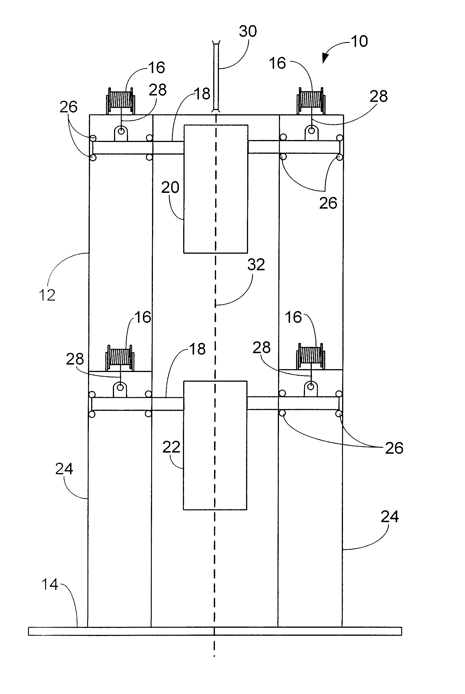
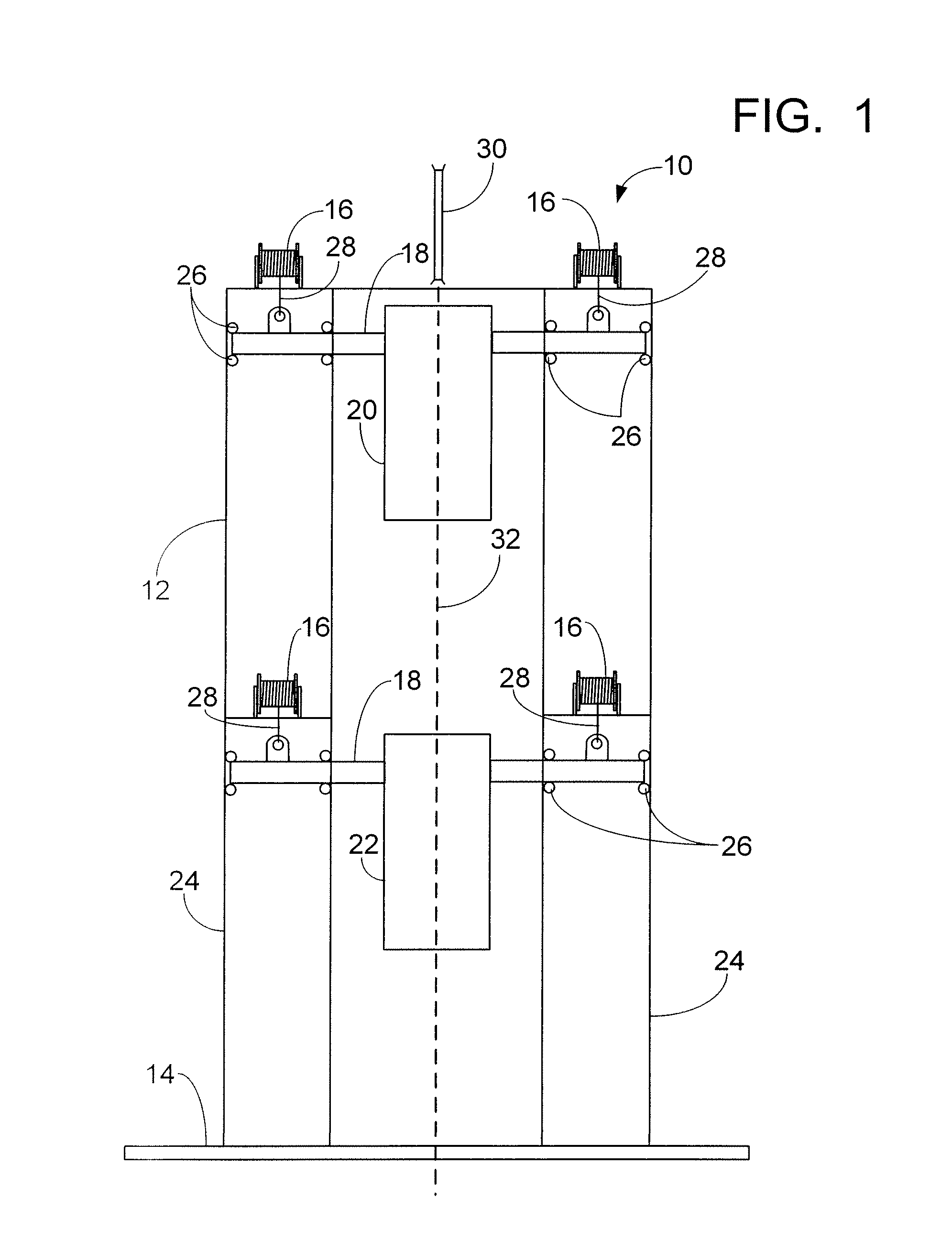
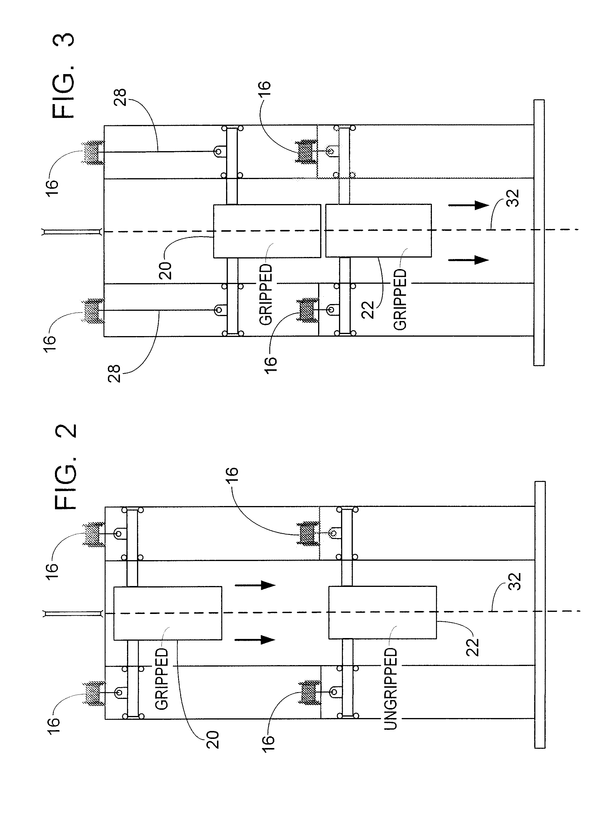
[0011]As seen in FIG. 1 the non-rigid product laying apparatus 10 is generally comprised of a tower 12 attached to the deck 14 of a product laying vessel, winches 16, trolleys 18, and upper and lower clamps 20, 22. For ease of illustration and clearly illustrating the inventive concept, it should be noted that work spaces, etc. are not shown in the drawings.

[0012]As seen in FIG. 1, the tower 12 has two legs 24 in which the trolleys 18 are movably received for vertical movement. The trolleys 18 move on wheels or rollers 26.

[0013]Upper and lower clamps 20, 22 are respectively mounted on the upper and lower trolleys 18 and are preferably long grip length clamps. Examples of long grip length clamps that have been used and are suitable for flexible product are a four meter long clamp with a capacity of 300 metric tons. By way of comparison, a ten meter long tensioner has been known to be required for up to 300 metric tons grip on a flexible product.

[0014]Winches 16 are mounted in each le...


PUM


Abstract

An arrangement for laying non-rigid product offshore that includes a dual long grip length clamp arrangement installed vertically into a tower in a similar manner to a J-lay trolley / clamp system. The invention differs from a J-lay arrangement in that two clamps are used and the clamps are configured for use with non-rigid product, i.e. they have a long grip length in order to spread the load evenly. Each clamp is mounted on a trolley and can travel vertically up or down. The upper clamp is arranged with a distance between it and the lower clamp such that the upper clamp can lower the non-rigid product a suitable distance before the lower clamp grips the non-rigid product so as to create as close as possible continuous movement as practical.

Description

FIELD AND BACKGROUND OF INVENTION[0001]The invention is generally related to the laying of product offshore and, more particularly, to an arrangement for the laying of non-rigid product.[0002]Non-rigid product such as flexible pipe, umbilical lines, or cable is currently laid using a tensioner based system with the tensioner either mounted in a vertical tower or horizontally on the deck of the product laying vessel. The maximum overboard tension is a function of the hold back capacity and the applicable grip length when applied to the coefficient of friction of the product coating.[0003]Rigid pipe can be laid through the J-Lay methodology whereby a clamp is used to lower sections of pipe in a regimented process of lower, weld on a new section of pipe, load, lower, weld, etc. The advantage of the clamp based J-Lay process is that high tensions can be achieved using a relatively lightweight tower arrangement due to the lowering scheme being based on multi-fall hook technology. To cons...

Claims


Application Information

Patent Timeline
Patent Type & Authority Applications(United States)
IPC IPC(8): F16L1/12
CPCF16L1/235F16L1/207
Inventor SCREATON, LEE DAVID
Owner J RAY MCCDERMOTT SA
Why Eureka
Try Eureka