Golf club head and method for predicting carry distance performance thereof

Active Publication Date: 2013-01-31
SUMITOMO RUBBER IND LTD
View PDF32 Cites 16 Cited by
  • Summary
  • Abstract
  • Description
  • Claims
  • Application Information

AI Technical Summary

Benefits of technology

[0004]It is therefore, an object of the present invention to provide a golf club head which can in

Problems solved by technology

The recent golf rules, however, limit a maximum valu

Method used


Image

  • Golf club head and method for predicting carry distance performance thereof
  • Golf club head and method for predicting carry distance performance thereof
  • Golf club head and method for predicting carry distance performance thereof

Examples


Example

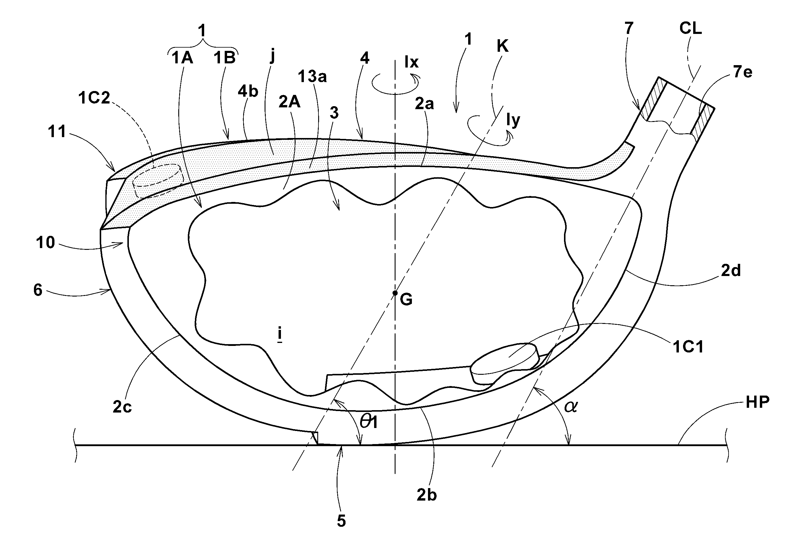
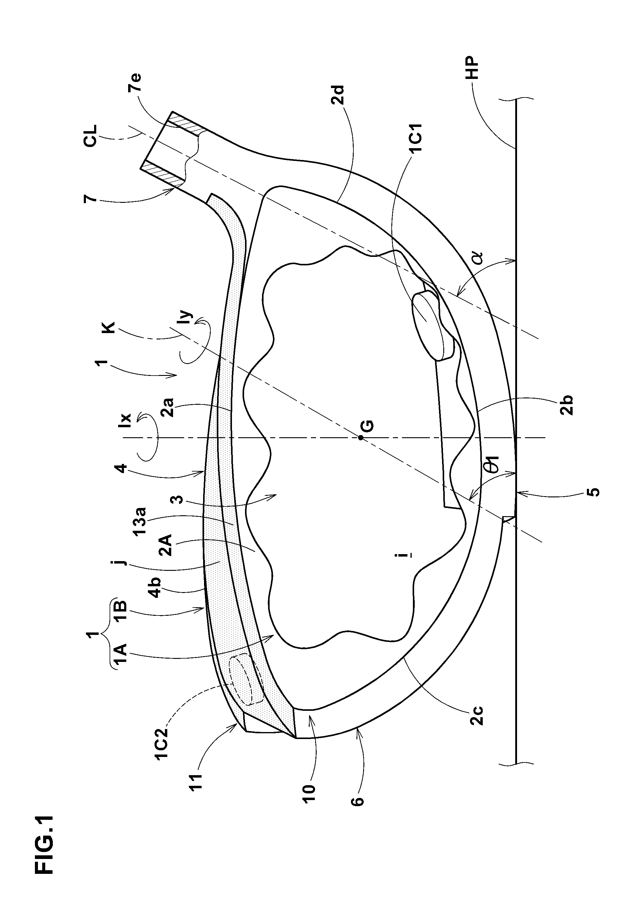
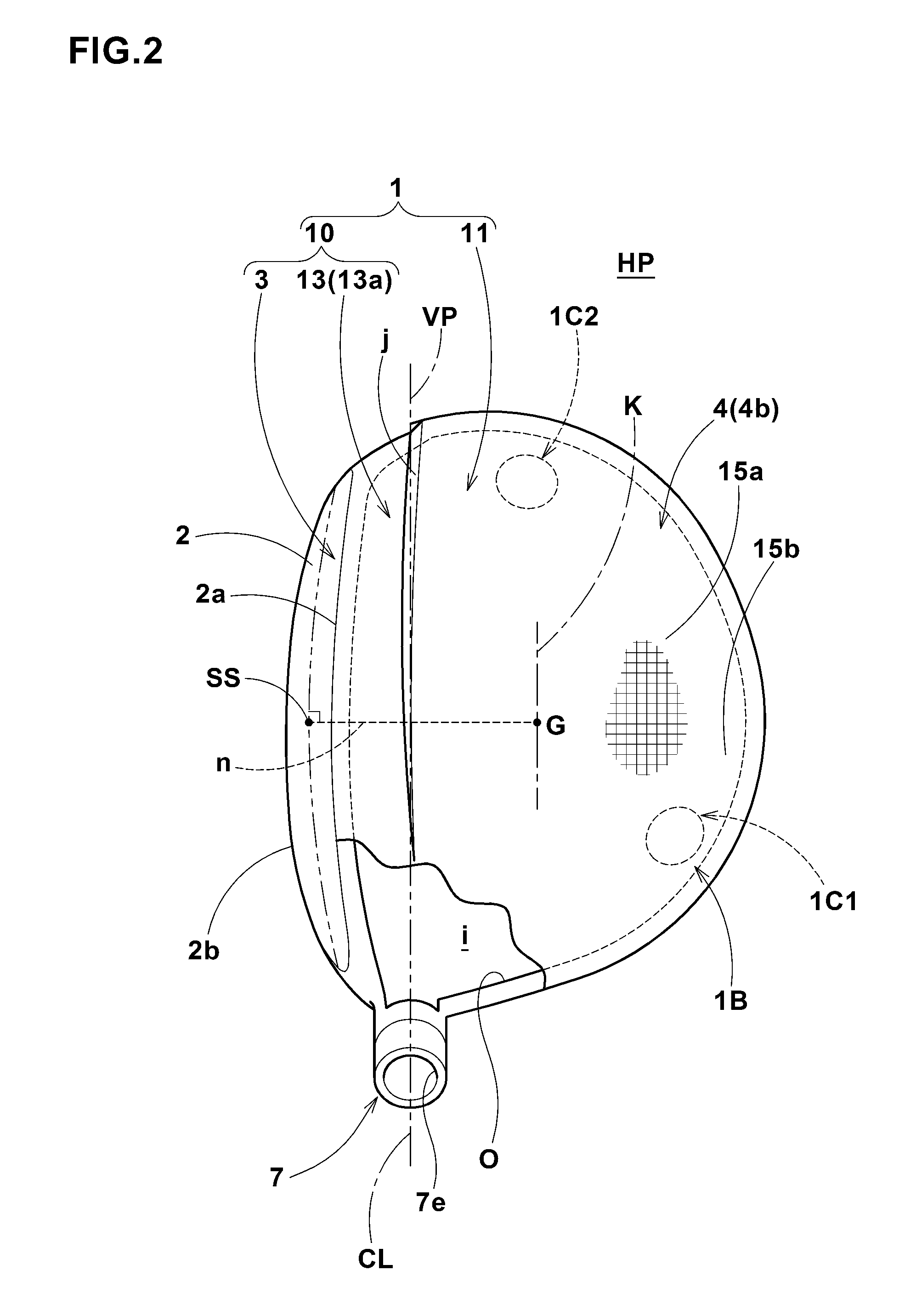
[0059]FIGS. 1 to 4 show the club head 1 as a first embodiment of the present invention.

[0060]The club head 1 in this embodiment is composed of a fore part 10 including the face portion 3, and an aft part 11 connected to the fore part 10 forming a stepped part j in the crown portion 4, sole portion 5 and side portion 6.

[0061]The fore part 10 includes, in addition to the face portion 3, a face turnback 13 extending for a short distance from the edge of the face portion 3 toward the back face 2B.

[0062]The face turnback 13 includes:

a crown front part 13a extending backward from the upper edge 2a of the club face 2A;

a sole front part 13b extending backward from the lower edge 2 of the club face 2A;

a toe front part 13c extending backward from the toe-side edge 2c of the club face 2A; and

a heel front part 13d extending backward from the heel-side edge 2d of the club face 2A.

[0063]As to the dimensions of the front parts 13a-13c in the front-back direction of the head, as shown in FIG. 2, th...

Example

[0075]FIG. 6 shows the club head 1 as a second embodiment of the present invention.

[0076]In the club head 1 in this embodiment, the club face 2A has a contour shape such that, in the front view of the head under the standard state, a straight line (th), which is defined as extending between a toe-side point (tm) on the edge of the club face 2A at the toe-side extreme end and a heel-side point (hm) on the edge of the club face 2A at the heel-side extreme end, is inclined at an angle δ of not less than 15 degrees with respect to the horizontal plane HP.

[0077]The club head 1 in this embodiment has a shape belonging to the conventional wood-type than the peculiar twisted shape of the first embodiment.

[0078]Even so, in such club head 1, it becomes possible to effectively distribute the mass to positions distant from the inclined axis K, therefore, it is possible for the club head 1 to have a mass distribution suitable for achieving the moment of inertia Iy and Ix within the above-mention...

Example

[0080]FIG. 8 shows the club head 1 as a third embodiment of the present invention.

[0081]The club head 1 in this the embodiment is provided in the hollow (i) with a ring-shaped weight member 1C surrounding the inclined axis K or a plurality of circular arc weight members 1C arranged circularly to surround the inclined axis K.

[0082]In the front view of the head under the standard state, the circle, along which the weight member or members 1CR are arranged, is inclined downwardly toward the heel from the toe preferably at an angle of 56 degrees with respect to the horizontal plane HP.

[0083]The club head 1 in this embodiment also has a shape belonging to the conventional wood-type than the peculiar twisted shape of the first embodiment.

[0084]such continuous ring-shaped weight member 1C or the circularly-arranged circular arc weight members 1C can be used in the above-mentioned first and second embodiments instead of a plurality of the weight members 1C having a shape like a block or but...


PUM


Abstract

A hollow golf club head has: a moment of inertia Ix around a vertical axis of 4500 to 5900 g sq·cm; and a moment of inertia Iy around an inclined axis of 5300 to 6800 g sq·cm, which satisfy Iy=<1.071 I×Ix+482 g sq·cm. The vertical axis passes through the center of gravity of the head under a standard state in which the head is set on a horizontal plane so that a shaft center line is inclined at a lie angle of 60 degrees with respect to the horizontal plane within a vertical plane and a club face lies at the loft angle. The inclined axis passes through the center of gravity of the head and is inclined downwardly toward the toe from the heel at 62 degrees with respect to the horizontal plane within a plane parallel with the above-mentioned vertical plane.

Description

BACKGROUND OF THE INVENTION[0001]The present invention relates to a golf club head capable of improving a carry distance of a stuck ball and a method for predicting the carry distance performance thereof.[0002]There has been known a golf club head which is, in order to improve the average carry distance of stuck balls, increased in the moment of inertia Ix around a vertical axis passing through the center of gravity of the head in a standard state in which the head is set on a horizontal plane so that the shaft center line is inclined at the lie angle within a vertical plane and the club face lies at the loft angle.In such golf club head, even if a ball is struck off the sweet spot of the club face, since the rotation of the club head around the vertical axis is inhibited, a decrease in the initial speed of the struck ball is lessened.Consequently, it has an advantage such that the carry distance loss is reduced.[0003]The recent golf rules, however, limit a maximum value of the mome...

Claims


Application Information

Patent Timeline
IPC IPC(8): A63B53/04A63B53/00A63B102/32
CPCA63B2053/0445A63B2053/0454A63B2209/023A63B53/0466A63B2053/0462A63B2053/0491A63B2053/0437A63B2053/0408A63B2053/0433A63B60/02A63B53/0408A63B53/0433A63B53/0437A63B53/0445A63B53/0454A63B53/0462
Inventor KIMIZUKA, WATARUONUKI, MASAHIDE
Owner SUMITOMO RUBBER IND LTD
Why Eureka
Try Eureka