
Dynamically limiting vehicle operation for best effort economy

a technology of dynamic limitation and vehicle operation, applied in the field of vehicles, can solve the problems of slow adoption of all-electric vehicles by large populations and the adverse effect of main electrical power storage devices

Active Publication Date: 2013-01-31
GOGORO
View PDF15 Cites 138 Cited by
  • Summary
  • Abstract
  • Description
  • Claims
  • Application Information

AI Technical Summary

Benefits of technology

The text is saying that using alternatives to combustion engines can help improve air quality and the health of many people.

Problems solved by technology

While the zero tail pipe emissions benefit of all-electric vehicles are appreciated, adoption of all-electric vehicles by large populations has been slow.
Performance of the main electrical power storage device may be adversely affected by a variety of conditions, such as current level of charge, temperature and history of use, including age and number of recharging cycles to which the main electrical power storage device has been subjected.

Method used


Image

  • Dynamically limiting vehicle operation for best effort economy
  • Dynamically limiting vehicle operation for best effort economy
  • Dynamically limiting vehicle operation for best effort economy

Examples


Embodiment Construction

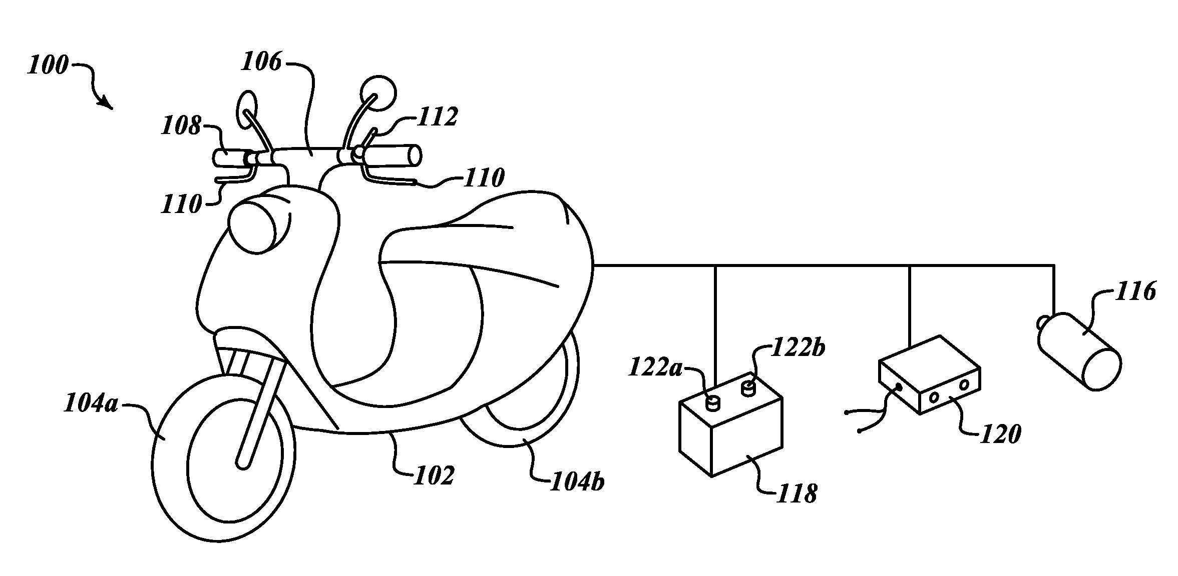
[0032]In the following description, certain specific details are set forth in order to provide a thorough understanding of various disclosed embodiments. However, one skilled in the relevant art will recognize that embodiments may be practiced without one or more of these specific details, or with other methods, components, materials, etc. In other instances, well-known structures associated with vending apparatus, batteries, super- or ultracapacitors, power converters including but not limited to transformers, rectifiers, DC / DC power converters, switch mode power converters, controllers, and communications systems and structures and networks have not been shown or described in detail to avoid unnecessarily obscuring descriptions of the embodiments.

[0033]Unless the context requires otherwise, throughout the specification and claims which follow, the word “comprise” and variations thereof, such as, “comprises” and “comprising” are to be construed in an open, inclusive sense that is a...


PUM


Abstract

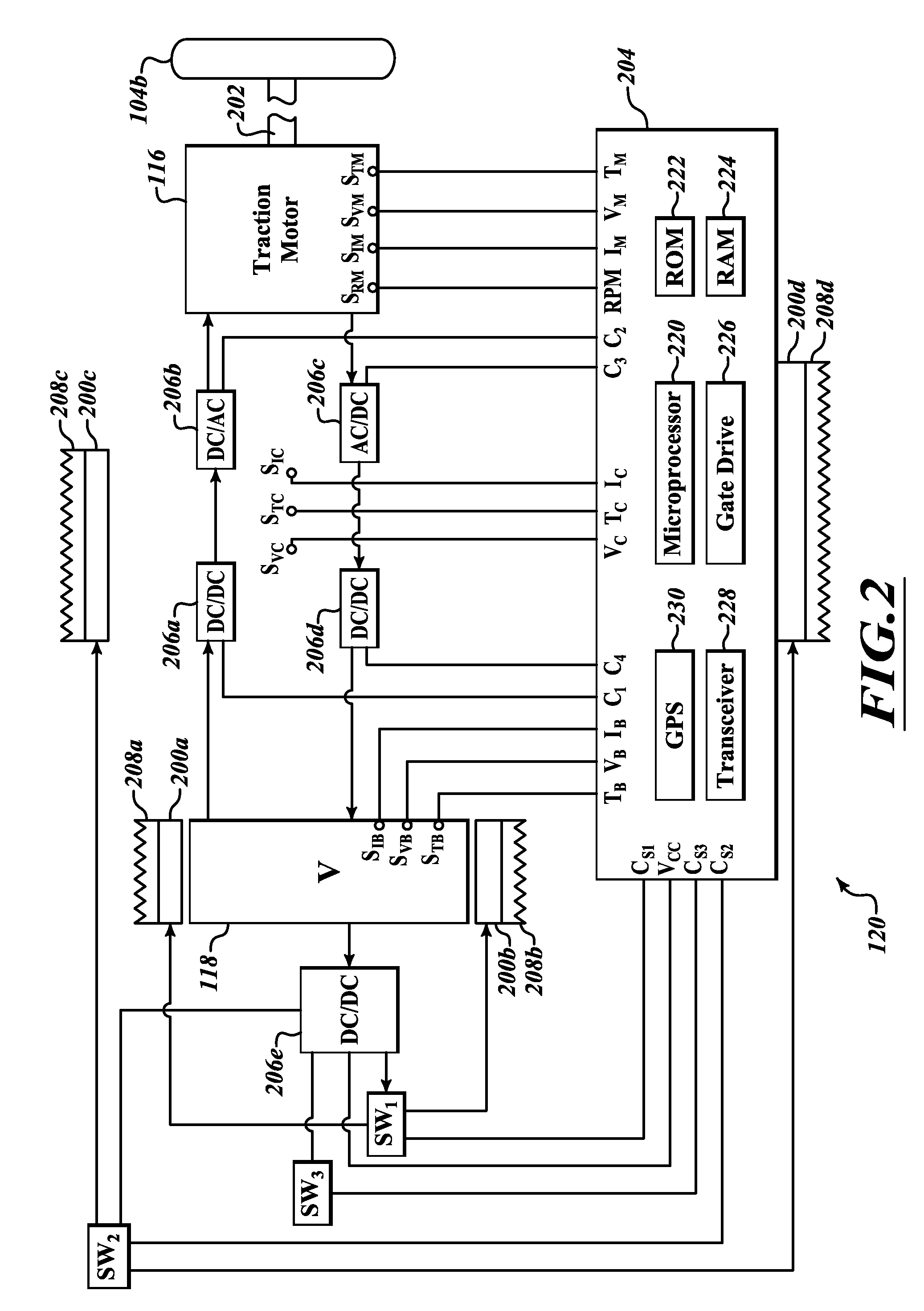
Vehicle operation (e.g., speed, acceleration) may be limited based on various conditions such as a current charge condition of an electrical energy storage devices (e.g., batteries, super- or ultracapacitors), history of such, conditions related to the vehicle (e.g., mileage, weight, size, drag coefficient), a driver or operator of the vehicle (e.g., history with respect to speed, acceleration, mileage) and / or environmental conditions (e.g., ambient temperature, terrain). A controller may control operation of one or more power converters to limit current and / or voltage supplied to a traction electric motor, accordingly.

Description

CROSS REFERENCE TO RELATED APPLICATIONS[0001]This application claims the benefit under 35 U.S.C. 119(e) of the filing date of U.S. provisional patent application Ser. No. 61 / 511,900 entitled “APPARATUS, METHOD AND ARTICLE FOR COLLECTION, CHARGING AND DISTRIBUTING POWER STORAGE DEVICES, SUCH AS BATTERIES” and filed Jul. 26, 2011 (Attorney Docket No. 170178.401P1), U.S. provisional patent application Ser. No. 61 / 647,936 entitled “APPARATUS, METHOD AND ARTICLE FOR COLLECTION, CHARGING AND DISTRIBUTING POWER STORAGE DEVICES, SUCH AS BATTERIES” and filed May 16, 2012 (Attorney Docket No. 170178.401P2), U.S. provisional patent application Ser. No. 61 / 534,753 entitled “APPARATUS, METHOD AND ARTICLE FOR REDISTRIBUTING POWER STORAGE DEVICES, SUCH AS BATTERIES, BETWEEN COLLECTION, CHARGING AND DISTRIBUTION MACHINES” and filed Sep. 14, 2011 (Atty. Docket No. 170178.402P1), U.S. provisional patent application Ser. No. 61 / 534,761 entitled “APPARATUS, METHOD AND ARTICLE FOR AUTHENTICATION, SECURI...

Claims


Application Information

Patent Timeline
Patent Type & Authority Applications(United States)
IPC IPC(8): B60L15/20B60L11/18
CPCH02J7/00Y02T10/7055Y02E60/12Y02T90/161Y02T10/7005Y02T10/7022Y02T90/16G07C5/00H01M10/4257H02J4/00H02J7/007G01C21/3476G06Q30/0253G06Q30/0259G06Q30/0267G06Q30/0639B60L3/003B60L3/0069B60L11/005B60L11/1822B60L11/1824B60L11/1846B60L11/1861B60L2200/12B60L2210/12B60L2210/14B60L2210/30B60L2230/16B60L2230/40B60L2240/70G07C5/0858Y02T10/7044Y02T10/705Y02T10/7241Y02T10/7233Y02T10/7225Y02T90/163Y02T90/168Y02T90/169Y02T90/124Y02T10/7011Y02T90/14Y02T90/128Y02T90/127Y04S30/12Y04S30/14E05B81/56Y02T10/7072B60L11/1838G06Q10/02Y02T10/7094Y02T10/92Y02T10/7291Y02T10/7258Y02T90/121H02J7/0013B60L1/003B60L1/02B60L1/14B60L3/0046B60L3/0061B60L7/06B60L7/14B60L7/22B60L15/2045B60L2220/14B60L2220/16B60L2220/46B60L2240/12B60L2240/14B60L2240/26B60L2240/421B60L2240/423B60L2240/427B60L2240/429B60L2240/525B60L2240/545B60L2240/622B60L2240/642B60L2240/645B60L2240/662B60L2250/10B60L2250/16B60L2250/18B60L2250/20B60L2250/22B60L2260/44B60L2260/52B60L2270/34B60L2270/46H01M10/425H01M10/441H01M10/482H01M2010/4278H01M2220/20H01M2220/30Y04S10/126Y04S50/10Y04S50/14B60L50/40B60L50/51B60L53/80B60L55/00B60L53/65B60L53/665B60L58/10B60L58/16B60L58/12B60L58/26B60L50/66B60L53/305B60L53/68Y10T70/7062G06Q30/0261H02J7/00045B60L58/25Y02E60/00Y02T10/64Y02T10/70Y02T10/72Y02T90/12Y02T90/167Y02E60/10B60L50/60B60L50/64B60L53/11B60L53/14B60L58/21G05F1/66G06F3/0608G06F3/0638G06F3/0671G07F9/001G07F17/12H02J7/00036B60L1/00B60L3/12B60L2200/24B60R25/04E05B47/0001E05B81/04G05B19/05G05B2219/15048G05B2219/15053G07C9/00309G07C2009/00769G07F15/003G07F15/005G07F15/006G07F17/0042H01M2010/4271H02J7/0045H02J11/00G01C21/3682
Inventor LUKE, HOK-SUM HORACETAYLOR, MATTHEW WHITING
Owner GOGORO
Learn More