Magnetic gate latch

a magnetic gate latch and magnetic technology, applied in the field of latches, can solve the problems of latches that cannot be closed properly latches that cannot be fixed,

Active Publication Date: 2013-02-07
D & D GROUP PTY LTD
View PDF16 Cites 1 Cited by
  • Summary
  • Abstract
  • Description
  • Claims
  • Application Information

AI Technical Summary

Benefits of technology

[0007]For at least one embodiment of the latch, in use one of the units is mounted on the swinging barrier, such as a door or gate, and the other is mounted on the adjacent structure, such as a door jamb or gate post. When the barrier is open the magnetic attraction is weak and the latch member and the latch receiver are relatively displaced by the biasing member. The element thus clears the latch receiver when the barrier is moved into closure. When the barrier is closed the magnetic attraction is relatively strong causing the relative displacement of the latch member into the latch receiver, securing the barrier.

Problems solved by technology

Some latches, however, fail to close properly because the latch mechanism is resistant to closing.
For example, if a gate is gently swung towards a closed position, the gate may not have enough momentum to work the latch mechanism causing latching failure.
In some circumstances the latch jams up or sticks.

Method used


Image

  • Magnetic gate latch
  • Magnetic gate latch
  • Magnetic gate latch

Examples


Embodiment Construction

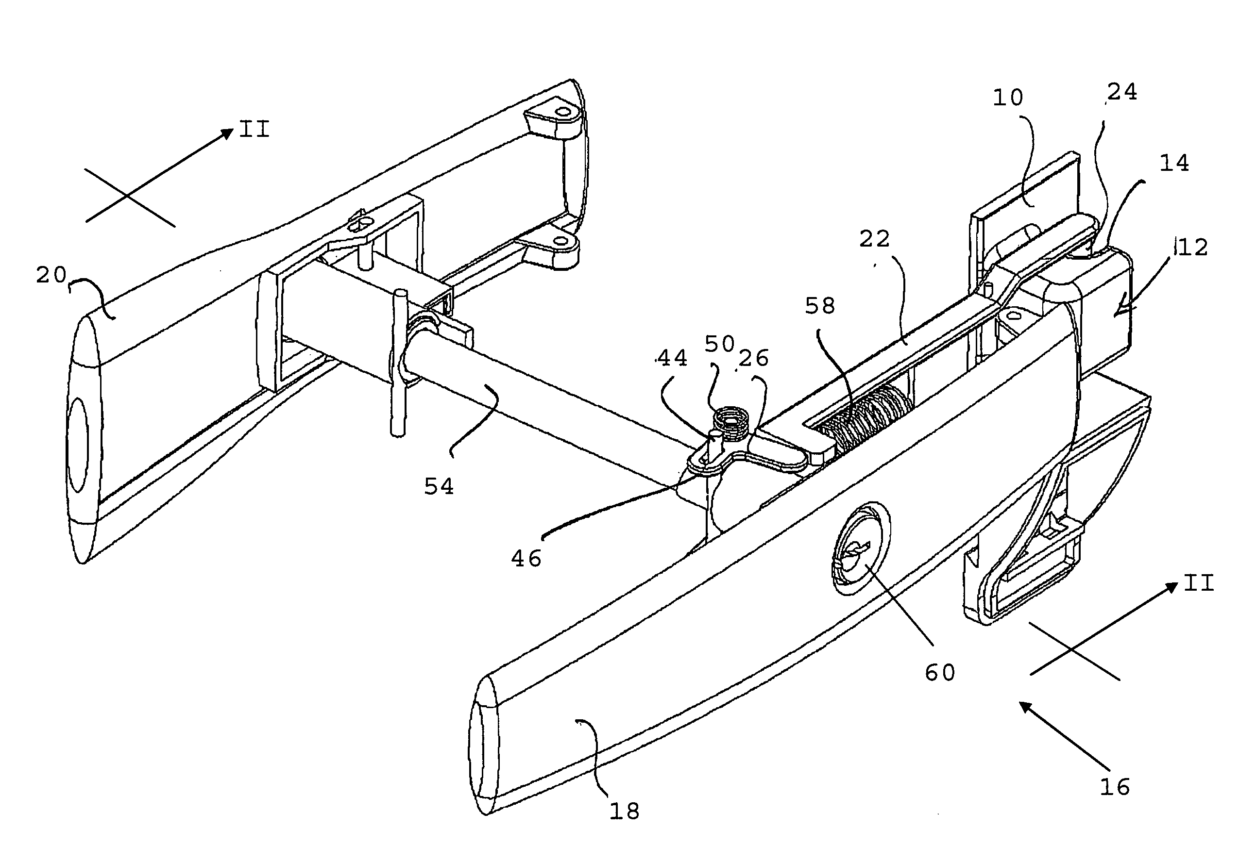
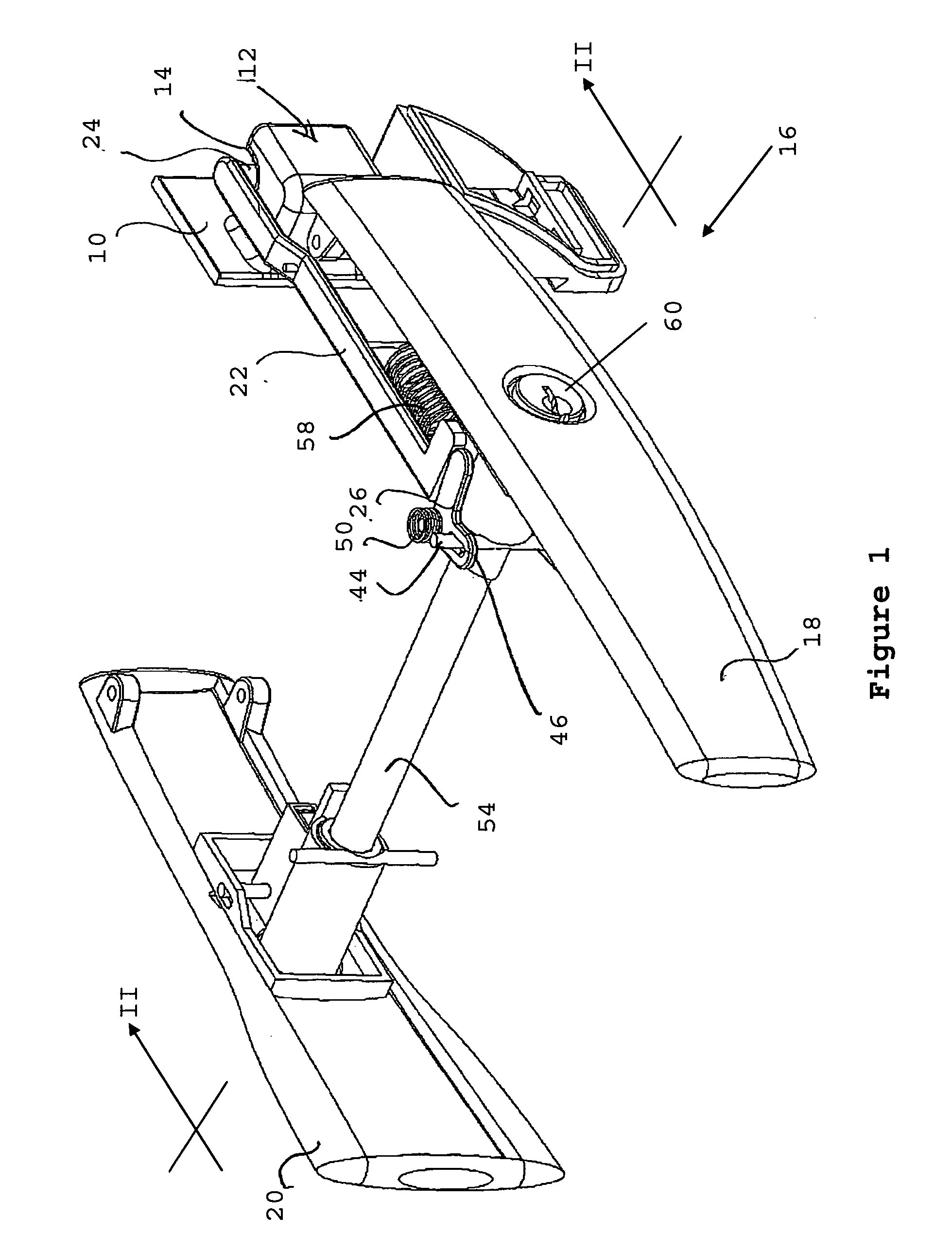
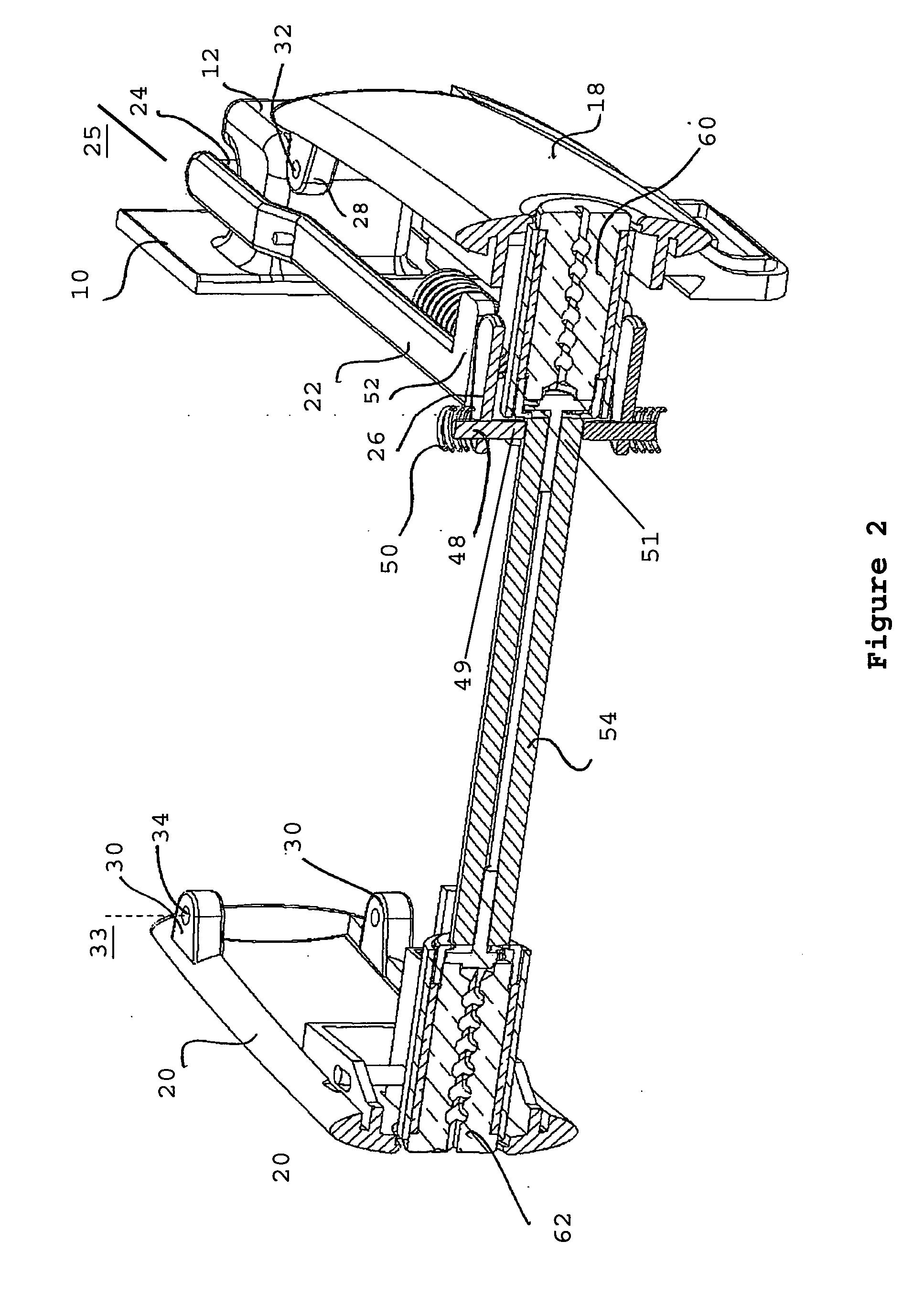
[0062]The embodiment of a latch shown in FIGS. 1 to 3 comprises a first unit 10 adapted to be mounted on a structure such as a gate post or door jamb and including a fixed latch receiver 12 having a latch shoulder 14, and a second unit 16 adapted to be mounted on a swinging barrier such as a door or gate and, as shown in FIG. 3, comprising a front unit 16A and a rear unit 16B which have respectively a lever arm in the form of a pull handle 18 and another lever arm in the form of a push bar 20 for actuating a latch mechanism. The lever arms are a form of human-mechanism interface. FIG. 4 shows a rear view of a latch mechanism of another but similar embodiment of a latch to that shown in FIGS. 1 to 3. Component parts in FIG. 4 which are similar to component parts in FIGS. 1 to 3 are similarly numbered. The latch mechanism comprises a mounting arm in the form of a slideable yoke 22 having a latch member 24 adapted to engage behind the latch shoulder 14. The latch has a linkage in the f...


PUM


Abstract

A latch has a magnet in one unit and an attracted element (e.g. ferromagnetic structure or another magnet) in second unit with a latching mechanism which operate under magnetic attraction. The latch has an actuator connected to a linkage to cause displacement of the magnet or the attracted element in a direction substantially normal to the axis of pivoting.

Description

FIELD OF THE INVENTION[0001]The present invention relates to latches and particularly but not exclusively to a magnetic latch for a swinging barrier such as a gate or a door.BACKGROUND OF THE INVENTION[0002]Latches for swinging barriers, such as gates and doors, generally provide security and safety. Some latches, however, fail to close properly because the latch mechanism is resistant to closing. For example, if a gate is gently swung towards a closed position, the gate may not have enough momentum to work the latch mechanism causing latching failure. In some circumstances the latch jams up or sticks.SUMMARY OF THE INVENTION[0003]In a first aspect, the invention provides a latch for a swinging barrier, the latch comprising:[0004]first and second units adapted for mounting respectively on the swinging barrier and an adjacent structure, one of the units having a first magnet and the other having an element magnetically attracted to the first magnet, such that when the first and secon...

Claims


Application Information

Patent Timeline
Patent Type & Authority Applications(United States)
IPC IPC(8): E05C19/16E05B21/06
CPCE05B1/0038E05B9/086E05B13/101E05B13/105E05B15/025E05C19/163E05B15/1635E05B53/00E05B63/22E05B65/0007E05C1/06E05B15/101Y10T70/7057Y10T70/7559Y10T292/11
Inventor CLARK, ANTHONY JOHNTUN, LINN THU YEINALEXANDER, JUSTIN
Owner D & D GROUP PTY LTD
Why Eureka
Try Eureka