

Pin Roller Type Pinion Device
a pinion device and roller type technology, applied in the direction of gearing, mechanical equipment, hoisting equipment, etc., can solve the problems of shortening the service life, deteriorating the transmission precision between, and unacceptable noise, so as to enhance the rupture strength and increase the wear resistan
- Summary
- Abstract
- Description
- Claims
- Application Information
AI Technical Summary
Benefits of technology
Problems solved by technology
Method used
Image

Examples
first embodiment
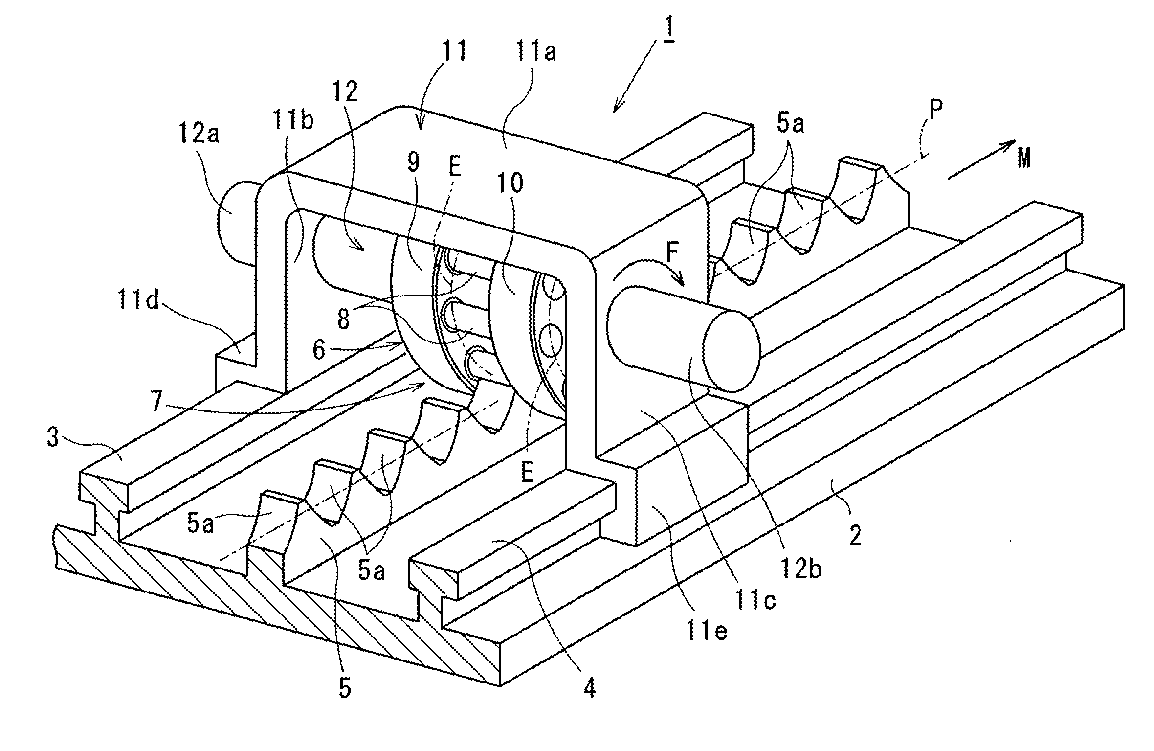
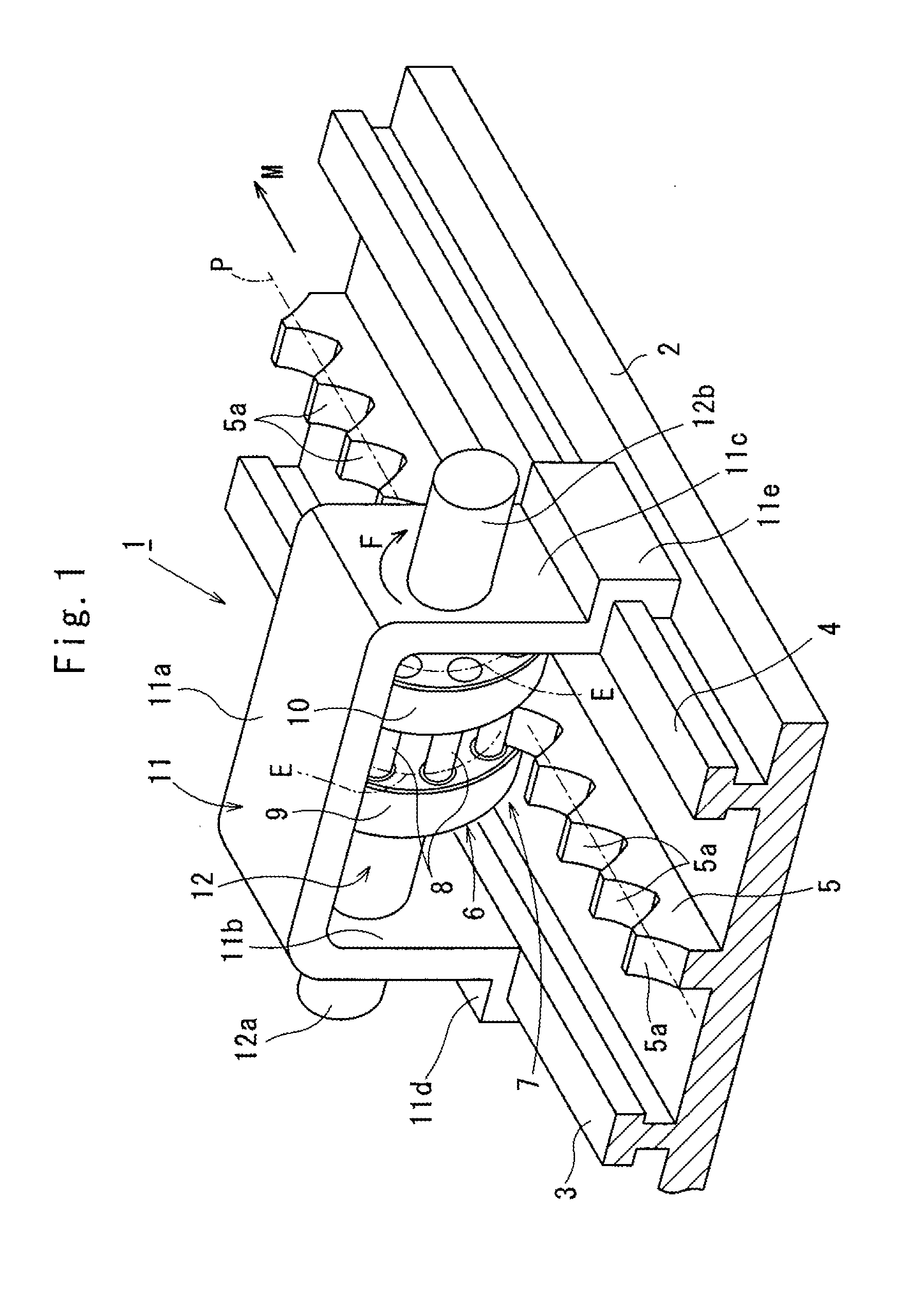
[0042]Referring to FIGS. 1 through 7 which show a pin roller type pinion device 7 according to the invention, as shown in FIG. 1, a rack-pinion device 1 has a basal plate 2 placed on a ground floor (not shown) in an assembly factory by way of example.
[0043]At a right and left side of the basal plate 2, there is provided conveyance rails 3, 4 each having a T-shaped cross section. At a middle portion of the basal plate 2 between the conveyance rails 3, 4, a rectilinear rack 5 is provided along its lengthwise direction M.
[0044]A length of the rack 5 is determined to meet an object to be used, and the upper surface of the rack 5 has multitude of teeth 5a defined based on a cycloid-curved profile continuously along a pitch line P.
[0045]The pin roller type pinion device 7 has a pinion 6 having a plurality of pin rollers 8, some of which engage with the teeth 5a of the rack 5, so that the pinion 6 rotates to run along the rack 5. By way of example, the number of the pin rollers 8 is ten wi...
second embodiment
[0067]FIGS. 8 and 9 show the invention in which annular first and second retainers 19, are used instead of the first and second inner races 15, 16.
[0068]As shown in FIG. 9, each of the first pin needles 17 has one end extended to have a jutted portion 17a, and having the other end extended to have a protruded portion 17b. The first retainer 19 has perforations 19a defined circumferentially, and the second retainer 10 has openings 20a arranged circumferentially.
[0069]As shown in FIG. 8, the jutted portions 17a are interfit into the corresponding perforations 19a of the first retainer 19, and the protruded portions 17b are interfit into the corresponding openings 20a of the second retainer 20, so that an array of the first pin needles 17 is annularly kept around one end portion 8a of the pin roller 8 as to define the first bearing 13. Between the neighboring first pin needles 17, there is provided a slight clearance Gs so that the first pin needles 17 are rollably arranged. The array ...
third embodiment
[0070]It is to be noted that since the second pin needles 18 have the same structure as the first pin needles 17, the relevant description is omitted in connection with the second bearing 14 and second pin needles 18. The same is true with the invention.
[0071]FIGS. 10 and 11 show a third embodiment of the invention which omits the first and second retainers 19, 20 of the second embodiment of the invention.
[0072]As shown in FIG. 11, the first pin needles 17 are annularly arranged around one end portion 8a of the pin roller 8 so as to form an integrated needle. Between the neighboring first pin needles 17, there is provided a slight gap Gp in order to be rollably arranged. The viscous lubrication oil such as e.g., grease (not shown) is applied to the first pin needles 17 and the one end portion 8a of the pin roller 8 so as to locate the first pin needles 17 in place.
[0073]In this situation, the grease connectedly arranges the first pin needles 17 circularly to form the first bearing 1...
PUM
 Abstract
Description
Claims
Application Information