Vessel comprising a stowable magnus-effect rotor

a rotor and magnus-effect technology, applied in the field of vessels, can solve the problems of rotors providing additional instability to the vessels, rotors being a great source of drag, and the failure of the rotor to provide any additional propulsion, so as to reduce the use of deck space

Active Publication Date: 2013-02-07
WINKLER JORN PAUL
View PDF2 Cites 10 Cited by
  • Summary
  • Abstract
  • Description
  • Claims
  • Application Information

AI Technical Summary

Benefits of technology

[0010]Thereto, a known vessel with a Magnus-effect rotor is characterised in that the motor drive is situated inside the cylinder. By having th

Problems solved by technology

However, in case of strong opposing winds essentially parallel to the desired sailing direction, or in wind conditions with severe gusts, the Flettner-rotor fails to provide any additional propulsion.
In these conditions the rotor proves to be a great source of drag to due to the wind hitting the relatively large frontal surface of the rotor.
Furthermore, in severe weather conditions with strong winds and high waves, the rotor proves to provide additional instability to the v

Method used


Image

  • Vessel comprising a stowable magnus-effect rotor
  • Vessel comprising a stowable magnus-effect rotor
  • Vessel comprising a stowable magnus-effect rotor

Examples


Embodiment Construction

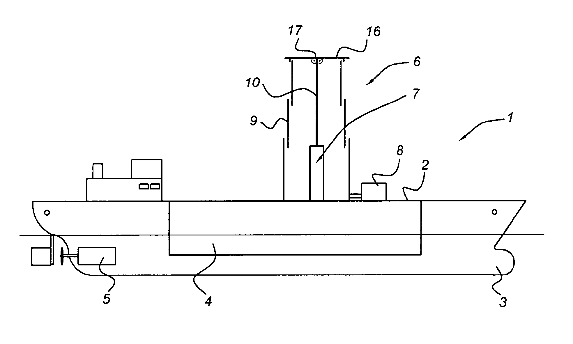
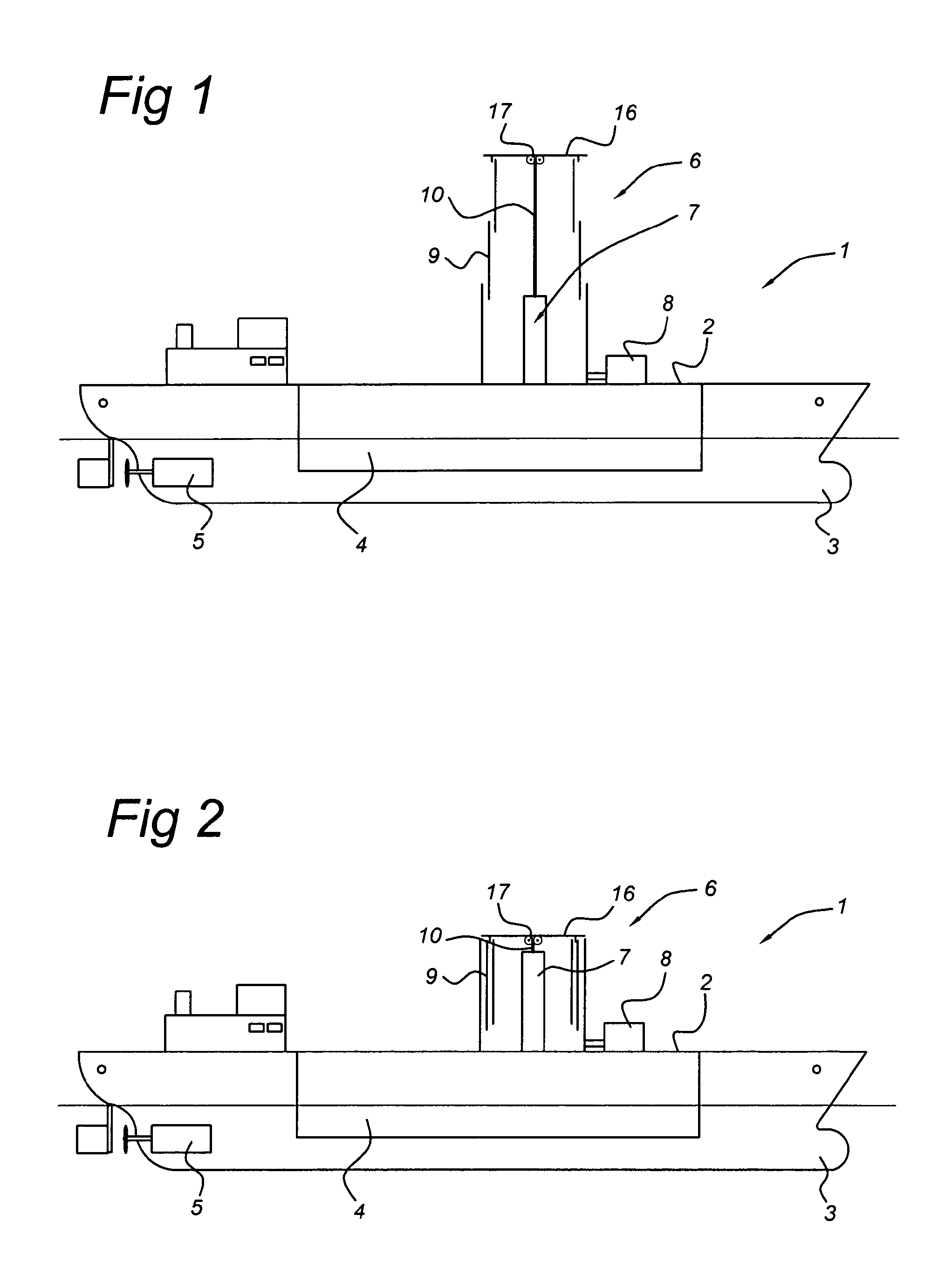
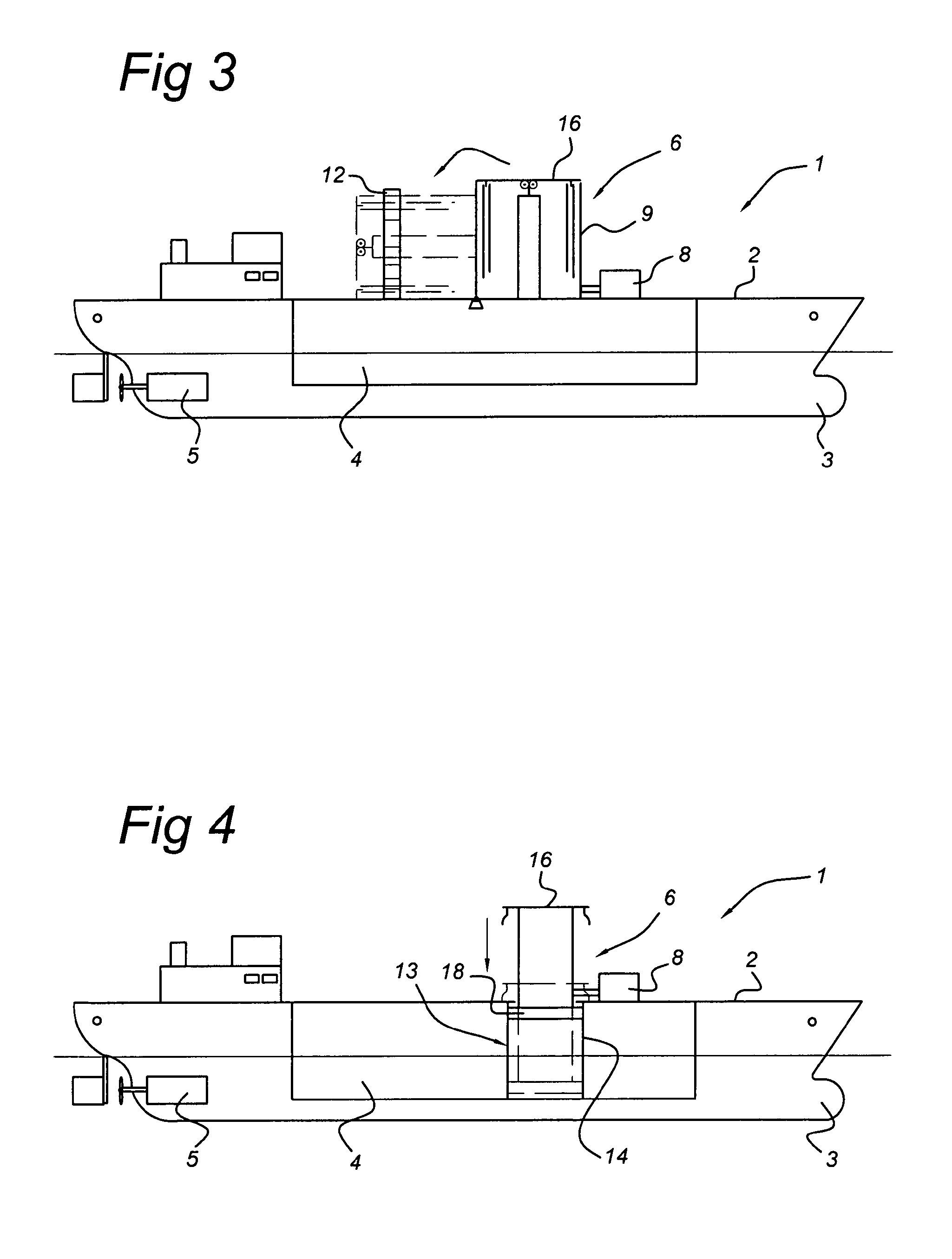
[0056]FIG. 1 shows a schematic side view of a vessel equipped with a telescopically retractable rotor in an extended, operational state, according to an embodiment of the invention; the vessel 1 is provided with a cargo compartment 4 for storing cargo. The vessel 1 is also equipped with a propulsion system 5 for propelling the vessel 1. The hull 3 comprises the forementioned cargo compartment 4. The upper part of the hull 3 is formed by the deck 2. The cylindrical rotor 6 is placed on the deck 2. Also situated on the deck 2 is a motor drive8 for rotating or spinning the rotor 6 to a desired rotational speed. The rotor 6 itself comprises several tubular segments 9. The tubular segments 9 are telescopically fitted into each other, with their longitudinal axes essentially in line with each other and their outer surfaces partly overlapping. Along the longitudinal axis of the rotor 6 a displacement member 7 is placed for extending the rotor 6 to its operational state, and for retracting ...


PUM


Abstract

A vessel includes a hull, a propeller for propulsion of the vessel and at least one rotatable cylinder which in its operational state is vertically mounted on the vessel, the cylinder having a rigid outer surface, a motor drive for rotating the cylinder around a longitudinal axis and a displacement member for displacing the cylinder to an inoperational position, wherein the motor drive is situated inside the cylinder.

Description

FIELD OF THE INVENTION[0001]The invention relates to a vessel comprising a hull, a propeller for propulsion of the vessel and at least one rotatable cylinder which in its operational state is vertically mounted on the vessel, the cylinder having a rigid outer surface, a motor drive for rotating the cylinder around a longitudinal axis and a displacement member for displacing the cylinder to an inoperational position.BACKGROUND OF THE INVENTION[0002]Such a Magnus-effect rotor is known from U.S. Pat. No. 4,602,584. It has long been known that a circular cylinder rotating about its longitudinal axis is capable of producing a lift force when placed in an air stream flowing perpendicular to the longitudinal axis of the cylinder, quite similar to the lift force produced by a wing when placed in a laminar air flow. This lift force is named after its discoverer, Heinrich Gustav Magnus, the German scientist who first investigated this phenomenon in 1853.[0003]The Magnus-effect was first appli...

Claims


Application Information

Patent Timeline
IPC IPC(8): B63H9/02
CPCY02T70/58B63H9/02Y02T70/5236
Inventor WINKLER, JORN PAUL
Owner WINKLER JORN PAUL
Why Eureka
Try Eureka