Thermal pressure relief device

a pressure relief device and thermal technology, applied in the direction of safety valves, valve arrangements, thin material handling, etc., can solve the problems of unsatisfactory rupture or bursting of the pressure vessel, large package size of the elongated bulb, etc., to achieve the effect of reducing the package size, reducing the manufacturing cost, and reducing the activation period

Active Publication Date: 2013-02-07
GM GLOBAL TECH OPERATIONS LLC
View PDF16 Cites 4 Cited by
  • Summary
  • Abstract
  • Description
  • Claims
  • Application Information

AI Technical Summary

Benefits of technology

[0005]In concordance and agreement with the present invention, a pressure relief device (PRD) including a trigger mechanism

Problems solved by technology

However, heat transfer to the PRD by the ignitable cord is not suitable in certain applications and occasionally unpredictable, which could result in an undesired rupture or bursting of the

Method used


Image

  • Thermal pressure relief device
  • Thermal pressure relief device

Examples


Embodiment Construction

[0014]The following detailed description and appended drawings describe and illustrate various embodiments of the invention. The description and drawings serve to enable one skilled in the art to make and use the invention, and are not intended to limit the scope of the invention in any manner.

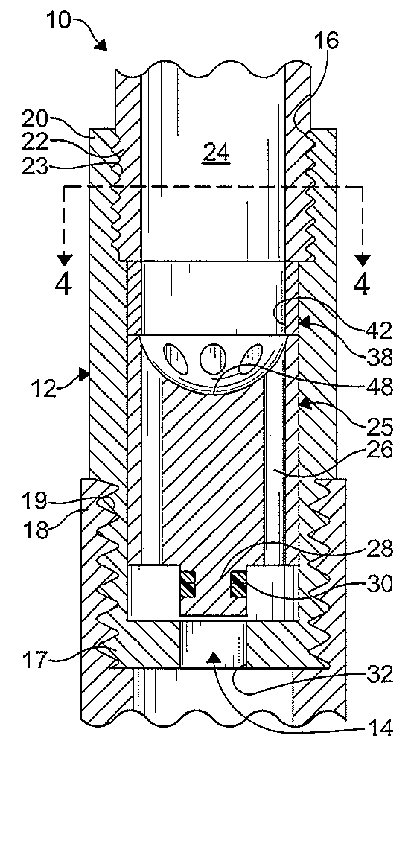
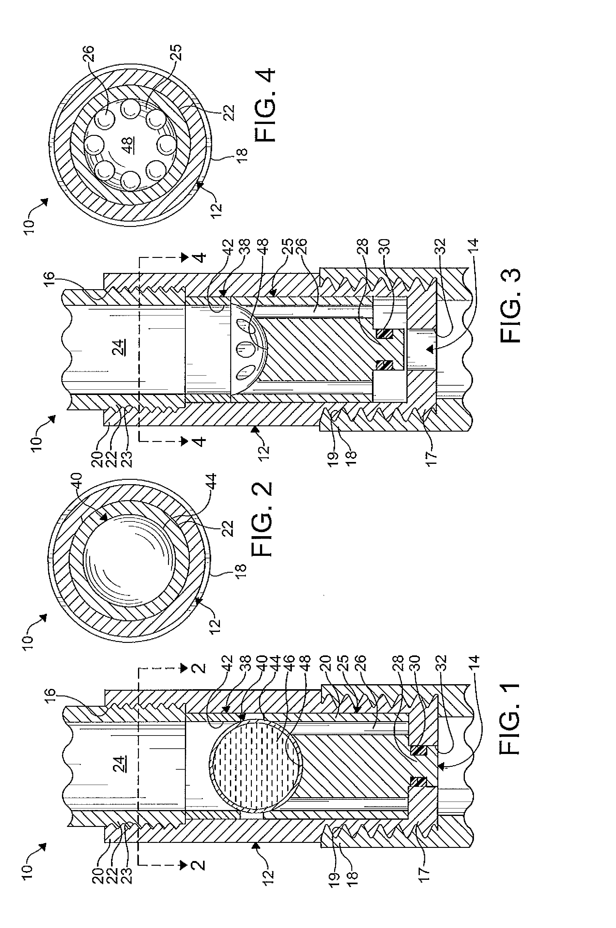
[0015]FIGS. 1-4 show a thermal pressure relief device (TPRD) 10 according to an embodiment of the present invention. The TPRD 10 shown includes a cylindrical housing 12. It is understood that the housing 12 can have any shape and size as desired. It is further understood that the housing 12 is formed from any suitable material such as a thermally conductive material, for example. The housing 12 includes a first aperture 14 and a second aperture 16. The first and second apertures 14, 16 are configured to allow a fluid (not shown) to flow through the housing 12. For example, the fluid may flow from a high pressure vessel (not shown) through the TPRD 10 to the atmosphere when the TPRD 10 is actua...


PUM


Abstract

A thermal pressure relief device (TPRD) including a housing having a movable member and a retainer disposed therein. The movable member is movable between an open position and a closed position. A trigger mechanism is disposed between the movable member and the retainer. The trigger mechanism holds the movable member in the closed position and includes a substantially spherical shaped body and a temperature sensitive material disposed in the body. The temperature sensitive material volumetrically expands with an increase in temperature until a predetermined temperature is attained and a breakage of the body occurs. When the body of the trigger mechanism breaks, the movable member is displaced from the closed position to the open position, allowing a fluid to flow through the TPRD.

Description

FIELD OF THE INVENTION[0001]The disclosure relates to a pressure relief device and, more particularly, to a pressure relief device including a thermally responsive trigger mechanism.BACKGROUND OF THE INVENTION[0002]The fuel cell has been proposed as a clean, efficient, and environmentally responsible power source for various applications. A plurality of fuel cells may be arranged to form a fuel cell stack capable of powering an electric vehicle. One example of the fuel cell is a Proton Exchange Membrane (PEM) fuel cell. In the PEM fuel cell, hydrogen is supplied as a fuel to an anode and oxygen is supplied as an oxidant to a cathode. A common technique for storing hydrogen is in a lightweight, high pressure vessel resistant to puncture. High pressure vessels containing the compressed hydrogen gas must have a desired mechanical stability and integrity that militates against a rupture or bursting of the pressure vessel from the internal pressure. It is also typically desirable to make...

Claims


Application Information

Patent Timeline
IPC IPC(8): F16K17/14F16K17/38
CPCF16K17/38Y10T137/1812Y10T137/1797
Inventor BREUER, PATRICKNETTESHEIM, STEFAN
Owner GM GLOBAL TECH OPERATIONS LLC
Why Eureka
Try Eureka