Side mounted air spring trailing arm suspension

Active Publication Date: 2013-02-07
ARVINMERITOR TECH
5 Cites 2 Cited by

AI-Extracted Technical Summary

Problems solved by technology

Military trailers are subjected to unique challenges due to the harsh environment in which they operate.
Suspensions for military trailers are conflicted by ...

Method used

[0037]By positioning the air springs outboard of the side rails as shown in FIG. 13, at full jounce there is less than 1.5 inches of available space between the axle and the frame. This makes a much more efficient use of the space, and reduces a cargo center of gravity for cargo being transported by the trailer by six inches. Further, the pivotal connection of the first and second arms can be brought closer to the side rails of the frame, which also simplifies the hanger bracket design as can be seen in the comparisons of the hanger bracket 90 in FIG. 13 with the hanger bracket 204 in FIG. 12. The configurations set forth in FI...

Abstract

A suspension includes first and second arms that connect a rigid axle to a frame structure. The first arm has one end configured for connection to a rigid axle structure and an opposite end adapted for connection to one lateral side of the frame structure. The second arm has one end configured for connection to the rigid axle structure and an opposite end adapted for connection to an opposite lateral side of the frame structure. The suspension includes a first air spring associated with the first arm and a second air spring associated with the second arm. The first and second air springs are configured to be positioned laterally outboard of the frame structure.

Application Domain

Interconnection systemsResilient suspensions +3

Technology Topic

Air springAir suspension +2

Image

  • Side mounted air spring trailing arm suspension
  • Side mounted air spring trailing arm suspension
  • Side mounted air spring trailing arm suspension

Examples

  • Experimental program(1)

Example

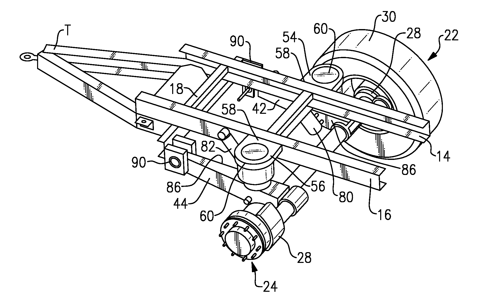
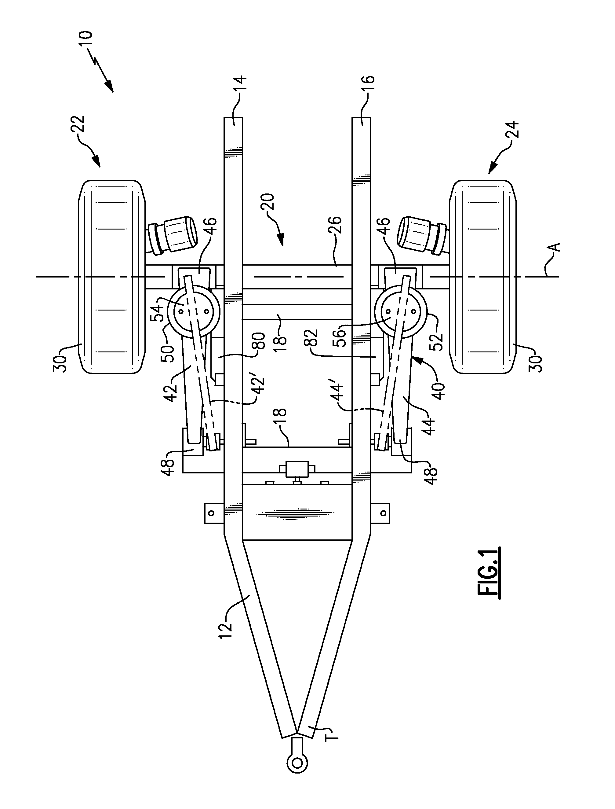
[0021]FIG. 1 shows a trailer 10 with a frame 12 having a first side rail 14 and a second side rail 16 that extend generally in a longitudinal direction along a length of the trailer 10. The trailer frame 12 includes one or more cross-rails 18 that extend generally in a lateral direction across a width of the trailer 10. The cross-rails 18 are connected at opposing ends to the first 14 and second 16 side rails. The trailer 10 also includes a tongue T configured for connection to a vehicle as known.
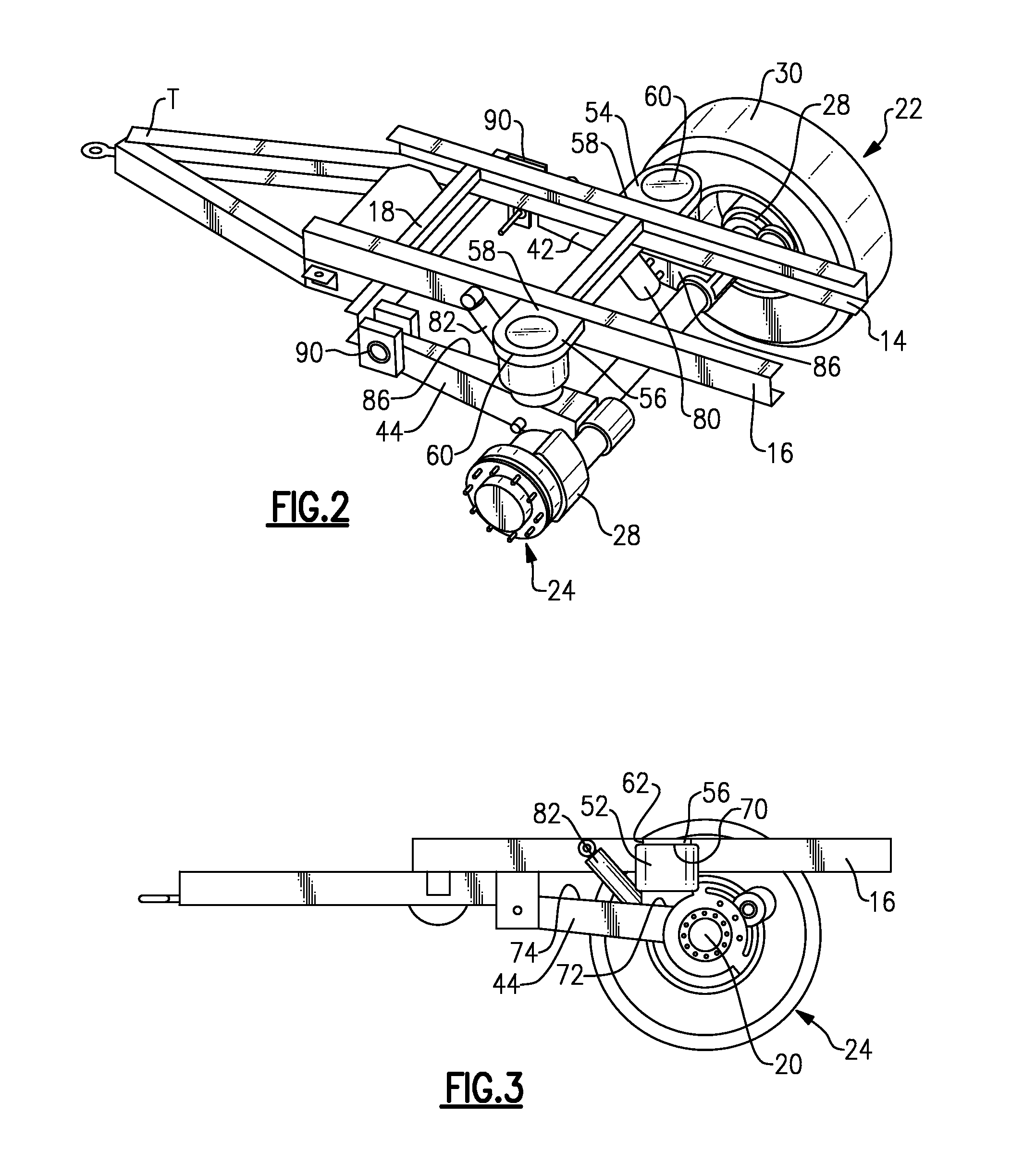
[0022]A rigid axle 20 includes first 22 and second 24 wheel assemblies that are laterally spaced apart from each other. The rigid axle includes an axle housing or axle tube 26 having one axle end mounted to the first wheel assembly 22 and an opposite axle end mounted to the second wheel assembly 24. The axle tube 26 defines an axis of rotation A about which the first 22 and second 24 wheel assemblies rotate. Each wheel assembly 22, 24 includes a brake assembly (schematically indicated at 28 in FIG. 2) and a tire 30. Only one tire 30 is shown in FIG. 2 for purposes of clarity.
[0023]A suspension assembly 40 is used to connect the rigid axle 20 to the frame 12. The suspension assembly 40 comprises a trailing arm, top mounted configuration. The suspension assembly 40 includes a first arm 42 and a second arm 44 that extend generally in a longitudinal direction. Each arm 42, 44 includes a first arm end 46 that is fixed to the axle tube 26 and a second arm end 48 that is pivotally connected to the frame 12.
[0024]In one example configuration, the second arm ends 48 of the first 42 and second 44 arms are mounted to one of the cross-rails 18. In this configuration, the first 42 and second 44 arms are generally parallel to the first 14 and second 16 side rails. In an optional arrangement, the second arm ends 48 of the first and second arms can be mounted directly to the first 14 and second 16 side rails, as indicated schematically at 42′, 44′ in FIG. 1. In this configuration, the second arm ends 48 of the first 42′ and second 44′ arms are divergent towards each other and are non-parallel to the first 14 and second 16 side rails.
[0025]The suspension assembly 40 includes first 50 and second 52 air springs that are respectively associated with the first 42 and second 44 arms. The air springs 50, 52 are mounted on the first 42 and second arms 44 outboard of the first 14 and second 16 side rails such that the first air spring 50 is located laterally between the first wheel assembly 22 and the first side rail 14 and the second air spring 52 is located laterally between the second wheel assembly 24 and the second side rail 16. The term “outboard” refers to a direction that is facing away from a center of the trailer and the term “inboard” refers to a direction that is facing toward the center of the trailer.
[0026]As shown in FIGS. 1 and 2, a first cantilevered bracket 54 is mounted to the first side rail 14 and extends in an outboard direction toward the first wheel assembly 22. A second cantilevered bracket 56 is mounted to the second side rail 16 and extends in an outboard direction toward the second wheel assembly 24. Inboard ends 58 of the first 54 and second 56 cantilevered brackets are respectively fixed to the first 14 and second 16 side rails, while outboard ends 60 of the first 54 and second 56 cantilevered brackets are unsupported.
[0027]As shown in FIGS. 4 and 5, the first 54 and second 56 cantilevered brackets each include a top plate 62 that defines the inboard 58 and outboard 60 ends, and first 64 and second 66 side braces that are longitudinally spaced apart from each other. In this example, the top plate 62 and first 64 and second 66 side braces are mounted to outboard facing sides of the first 14 and second 16 side rails. The brackets shown in these figures are just one example of a bracket structure, it should be understood that other bracket configurations could also be used.
[0028]As shown in FIGS. 2-3, each air spring 50, 52 includes an upper surface 70 and a lower surface 72. The lower surfaces 72 are supported on respective upper surfaces 74 of the first 42 and second 44 arms in a top mount configuration. The upper surfaces 70 are mounted to downwardly facing surfaces of the top plates 62 of the first 54 and second 56 cantilevered brackets. Any type of mounting structure and hardware can be used to attach the air springs 50, 52 to the top plates, such as fasteners for example.
[0029]The suspension assembly 40 also includes first 80 and second 82 shock absorbers that are respectively associated with the first 42 and second 44 arms. In the example shown in FIGS. 1-3, the shock absorbers 80 and 82 are mounted outboard of the first 14 and second 16 side rails. In this configuration, each shock absorber 80, 82 includes a first end 84 that is fixed to an inboard facing surface 86 (FIG. 2) of one of the first 42 and second 44 arms and a second end 88 that is fixed to the outboard facing side of one of the first 14 and second 16 side rails. FIG. 3 shows this outboard mounting configuration of both the second air spring 52 and second shock absorber 82 being located outboard of the second side rail 16.
[0030]Hanger brackets 90 are used to mount the second arm ends 48 of the first 42 and second 44 arms to the first 14 and second 16 side rails. As shown in FIGS. 4-5, the hanger brackets 90 include a top plate 92 and a pair of laterally spaced side walls 94 extending downwardly from the top plate 92. An end plate 96 inter-connects the side walls 92 and top plate 92 on one bracket end leaving the opposite end and the bottom of the bracket open. In the example shown in FIGS. 1-3, the end plate 96 is fixed to the cross-rail 18. In an alternate mounting configuration, the hanger bracket could also be mounted to the side rails.
[0031]FIGS. 4-5 show another example of a trailer frame 12′. In this example, in addition to the cross-rails 18′, the trailer frame 12′ also includes at least one sling lifting structure 100 that extends in the lateral direction and is connected to the first 14′ and second 16′ side rails. The sling lifting structure 100 comprises an interface for attachment to an air-lifting device such that a helicopter can pick up the trailer 10 and air-lift the trailer 10 from one location to another location.
[0032]The trailer frame 12′ shown in FIGS. 4-5 can also include an additional sling lifting structure 100′ that is longitudinally spaced from the sling lifting structure 100, and which is located at a rear of the trailer 10. Also shown in this example configuration are additional cross-rails 18′ which further strengthen the frame 12 compared to the configuration shown in FIGS. 1-3. The first 50′ and second 52′ cantilevered brackets are generally located centrally between the sling structures 100, 100′; however, other mounting locations could also be used. The same hanger brackets 90 are used to connect the second arm ends 48 of the first 42 and second 44 to the frame; however, in this example the hanger brackets 90 are fixed to the sling lifting structure 100.
[0033]FIGS. 6 and 7 show the rigid axle 20 and the suspension assembly 40 in an uninstalled condition. In this example, the shock absorbers 80, 82 are mounted in an inboard mounting configuration. Pivot mounts 110 are located on inboard facing surfaces 112 of the first 42 and second 44 arms. Also shown are optional pivot mounts 110′ on the outboard facing surfaces of the first 42 and second arms. The first arm ends 46 of the first 42 and second 44 arms are mounted to the axle tube 26 with axle wraps 114. Other mounting configurations could also be used.
[0034]FIGS. 8-11 are similar to FIGS. 1-3 with the exception that the second arm ends 48 of the first 42 and second 44 arms are mounted to the sling lifting structure 100 with hanger brackets 90. In this configuration the first 42 and second 44 arms extend generally parallel to the first 14′ and second 16′ side rails.
[0035]In each of the configurations, the first 12, 12′ and second 14, 14′ side rails have a lower surface and an upper surface spaced vertically above the lower surface. The first 50, 50′ and second 52, 52′ cantilevered brackets are configured to be mounted to the upper surface such that an upper surface of the first 50, 50′ and second 52, 52′ air springs is generally aligned with the upper surface of the first 14, 14′ and second 16, 16′ side rails. Further, in each of the configurations, the first 50, 50′ and said second 52, 52′ air springs are longitudinally offset from overlapping with the axle tube 26.
[0036]Positioning the air springs outboard of the side rails of the trailer frame provides several benefits compared to prior configurations. FIG. 12 shows one example of a prior configuration which includes a trailer frame side rail 200 and a suspension arm 202 that is pivotally mounted at one end with a hanger bracket 204 to the side rail 200 and fixed to a rigid axle structure 206 at an opposite end. A lower surface of an air spring 208 is supported on an upper surface 210 of the suspension arm 202. An upper surface of the air spring 208 is mounted to a lower surface 212 of the side rail 200. A shock absorber 214 has one end mounted to an inboard side of the suspension arm 202 and an opposite end mounted to an inboard side of the side rail 200. FIG. 12 shows this traditional trailing arm installation at full jounce, i.e. maximum compression of the wheel toward the frame. In the prior art configuration, there is over seven inches of space still left between the axle and the bottom of the frame.
[0037]By positioning the air springs outboard of the side rails as shown in FIG. 13, at full jounce there is less than 1.5 inches of available space between the axle and the frame. This makes a much more efficient use of the space, and reduces a cargo center of gravity for cargo being transported by the trailer by six inches. Further, the pivotal connection of the first and second arms can be brought closer to the side rails of the frame, which also simplifies the hanger bracket design as can be seen in the comparisons of the hanger bracket 90 in FIG. 13 with the hanger bracket 204 in FIG. 12. The configurations set forth in FIGS. 1-11 and 13 also provide reduced scrub load stress at the suspension arm to axle connection as compared to the traditional configuration of FIG. 12.
[0038]At ride height, i.e. a height between a center of the axle and the bottom of the frame during a normal operating condition, the subject configuration allows the trailer bed height to be lowered compared to prior configurations. This simplifies loading and provides increased rollover resistance without decreasing mobility. Further, the low bed height simplifies the trailer tongue mounting which now may possibly be configured to be an extension of the trailer floor structure.
[0039]The cantilevered brackets also provide advantages compared to prior designs without such brackets. The brackets take the input loads from the top of the springs which takes the twisting load out of the trailer structure. Also, trailers that are sling transportable by helicopter can use standard trailing arm suspension with cantilevered air spring supports if the hanger bracket is connected to another structure such as the sling lifting structure as described above.
[0040]The subject suspension assembly provides both high suspension travel for mobility in combination with a low bed height for roll stability and ease of cargo loading. The suspension is extremely durable without being excessively heavy, while still also providing the desired amount of ground clearance. By mounting the air springs outside of the trailer frame, i.e. outboard of the side rails, the air springs and the frame occupy the same vertical space without increasing the bed height. Further, as described above, the trailing arm suspension is a top mount configuration so that ground clearance is not sacrificed. The mounting of the air springs outside and next to the trailer frame allows the top mount suspension to achieve ride heights that were previously only possible with “underslung” or low mount suspensions. These types of suspensions cannot be used for the applications described above because underslung suspensions sacrifice ground clearance. An underslung suspension also has problems in these applications because the air spring is behind the axle and is exceptionally tall due to the high travel nature of a military trailer suspension.
[0041]Although a preferred embodiment of this invention has been disclosed, a worker of ordinary skill in this art would recognize that certain modifications would come within the scope of this invention. For that reason, the following claims should be studied to determine the true scope and content of this invention.

PUM

no PUM

Description & Claims & Application Information

We can also present the details of the Description, Claims and Application information to help users get a comprehensive understanding of the technical details of the patent, such as background art, summary of invention, brief description of drawings, description of embodiments, and other original content. On the other hand, users can also determine the specific scope of protection of the technology through the list of claims; as well as understand the changes in the life cycle of the technology with the presentation of the patent timeline. Login to view more.
Why Eureka
Try Eureka