

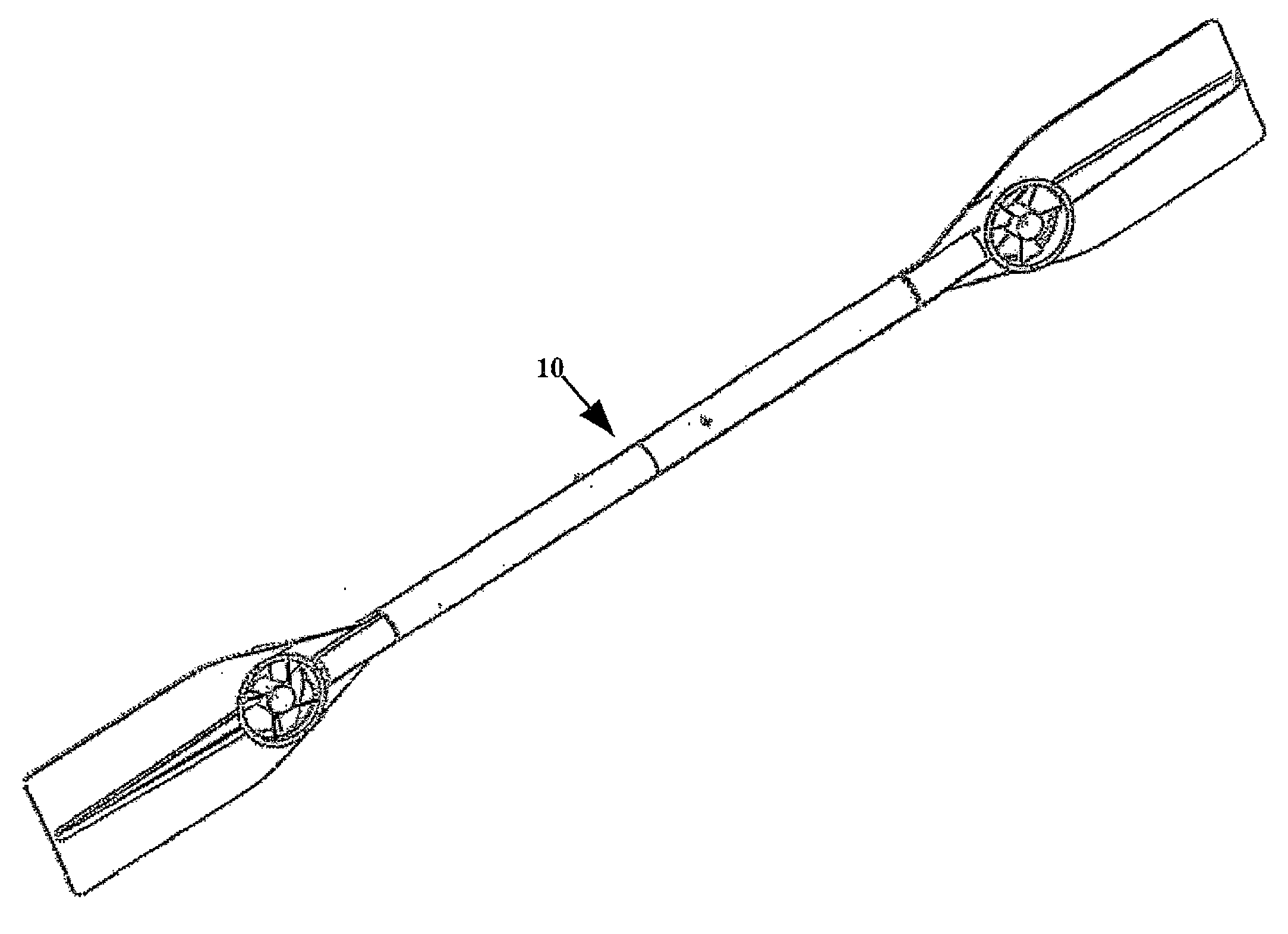
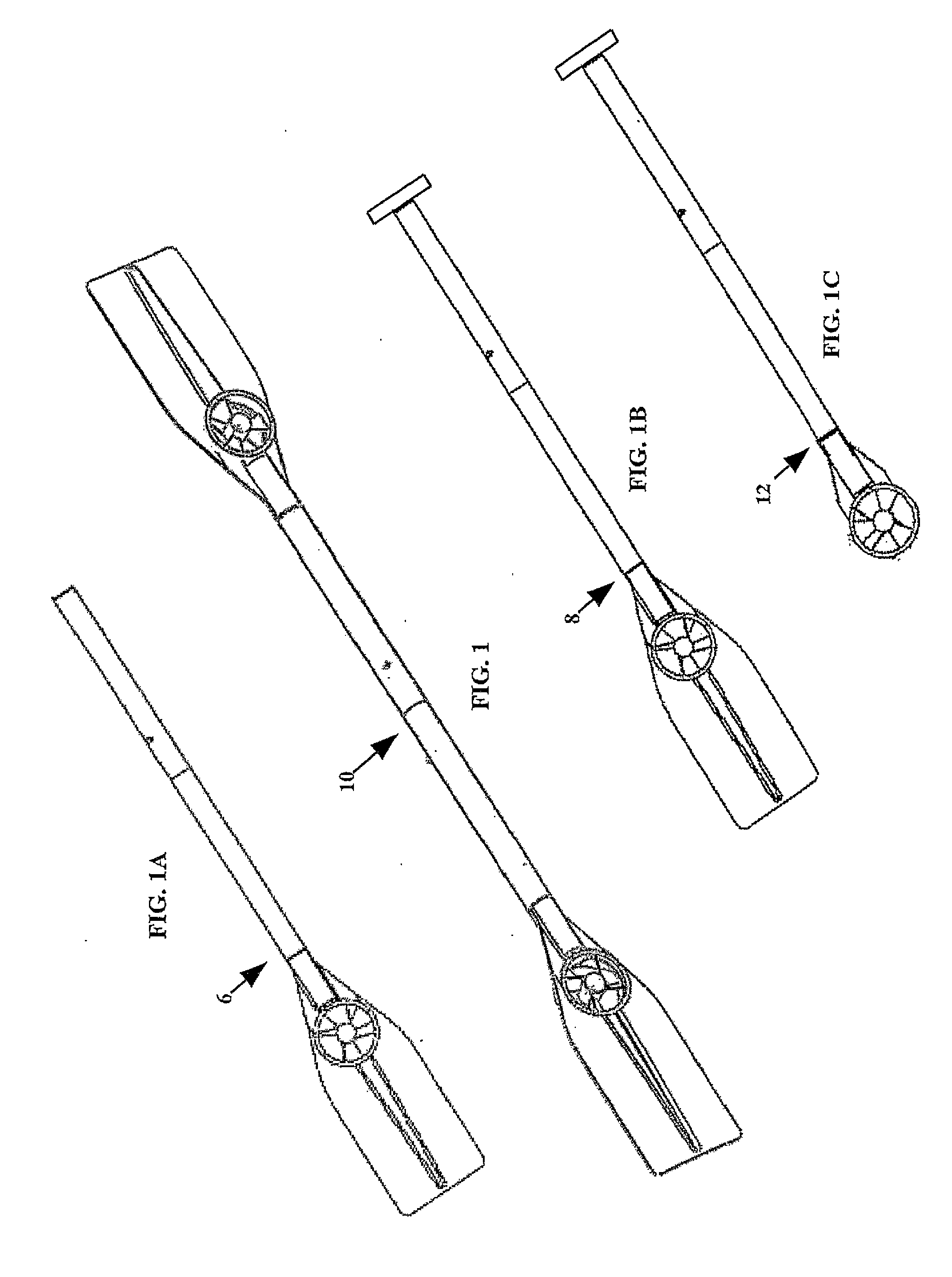
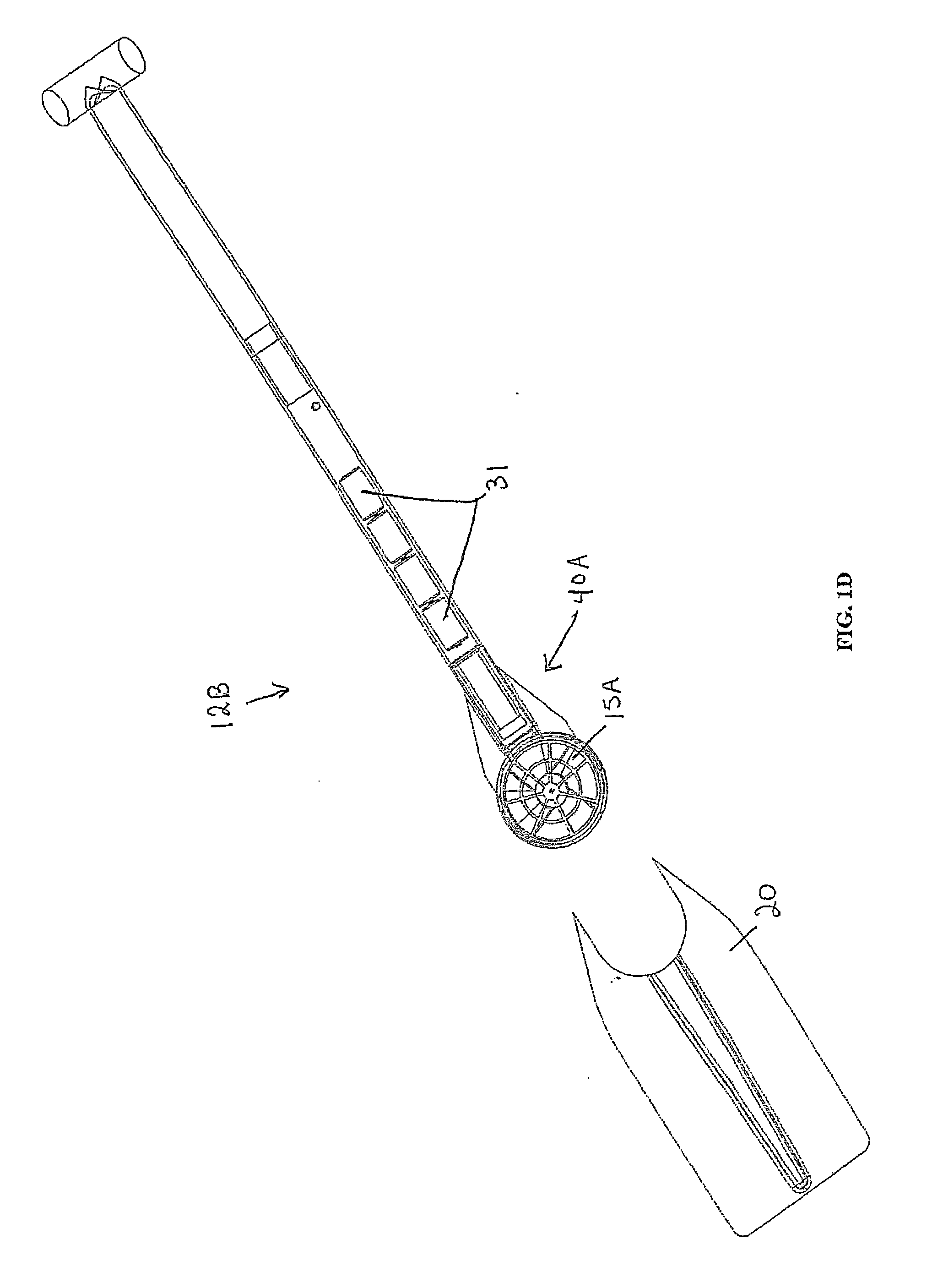
Combination hand-held multi-directional propulsion device, and powered oar/paddle for rowboat, canoe, kayak, and the like
a multi-directional propulsion and hand-held technology, applied in the field of oars or paddles, can solve the problems of not dramatically ease the burden of rowers for a sustained period of use, and the addition of strength requirements may preclude the use of many recreational rowers, and achieve the effect of easy removal of blades and easy conversion
- Summary
- Abstract
- Description
- Claims
- Application Information
AI Technical Summary
Benefits of technology
Problems solved by technology
Method used
Image

Examples
Embodiment Construction
[0077]There are many considerations which impact the design of a shaft and blade for levering a paddlesports boat, whether it be an oar for rowboats (sweep oar rowing or sculling), or a single-bladed paddle with a handle for canoeing, or a double-bladed paddle for kayaking. In each case, appropriate compromise and resolution between conflicting considerations are aimed at improving performance of the rower / paddler. But, the kind of performance being sought by one rower may be different than the kind of performance, or amount of performance, being sought by different occupants of the various paddlesports boats.
[0078]The primary objective in designing a levering device is to help the user achieve the most efficient stroke in order to propel the paddlesports boat forward according to the user's expertise. In general, the greater the mass of water that the blade is able to “grip,” the greater the resistance against which the paddler can lever him / herself and propel the paddlesports boat...
PUM
 Abstract
Description
Claims
Application Information