Self-propelled surface milling cutter

Active Publication Date: 2013-02-14
LIEBHERR COMPONENTS BIBERACH GMBH
View PDF6 Cites 5 Cited by
  • Summary
  • Abstract
  • Description
  • Claims
  • Application Information

AI Technical Summary

Benefits of technology

[0030]To prevent in particular said sealing device between the drive parts rotatable relative to each other from experiencing any axial, radial and/or angular displacements, which would lead to leakages and endanger the dust tightness, the stationary and rotating drive parts not only are supported on each other in an articulated manner by one bearing each, but are supported on each other and fixed axially to each other by a plurality of bearing points with a large supporting distance and hence in a flexurally rigid manner.
[0031]In accordance with a development of the present disclosure, the anti-friction bearing arrangement at the drive unit advantageously comprises a bearing point directly below or directly beside the sealing device as well as a bearing point distinctly spaced from the sealing device, so that on the whole a large supporting distance is achieved and the bearing as a whole is flexurally rigid. At the same time, a radial offset at the sealing device is completely inhibi

Problems solved by technology

A neat sealing of said housing parts, however, not only is necessary to avoid oil leakage, but also due to the often dusty operating conditions.
A dust input into the interior of the housing and hence into the transmission and the electric motor would drastically shorten the useful life of the motor-transmission unit, so that suitable measures also are required against dust input into the motor.
However, this necessitates a more or less expensive design of the drum supporting frame.
In addition, w

Method used


Image

  • Self-propelled surface milling cutter
  • Self-propelled surface milling cutter
  • Self-propelled surface milling cutter

Examples


Embodiment Construction

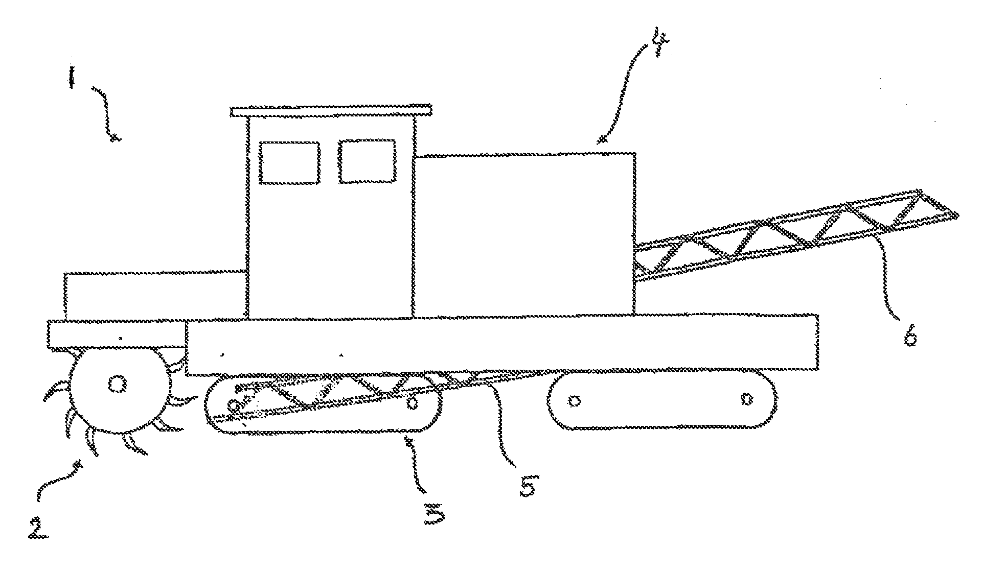
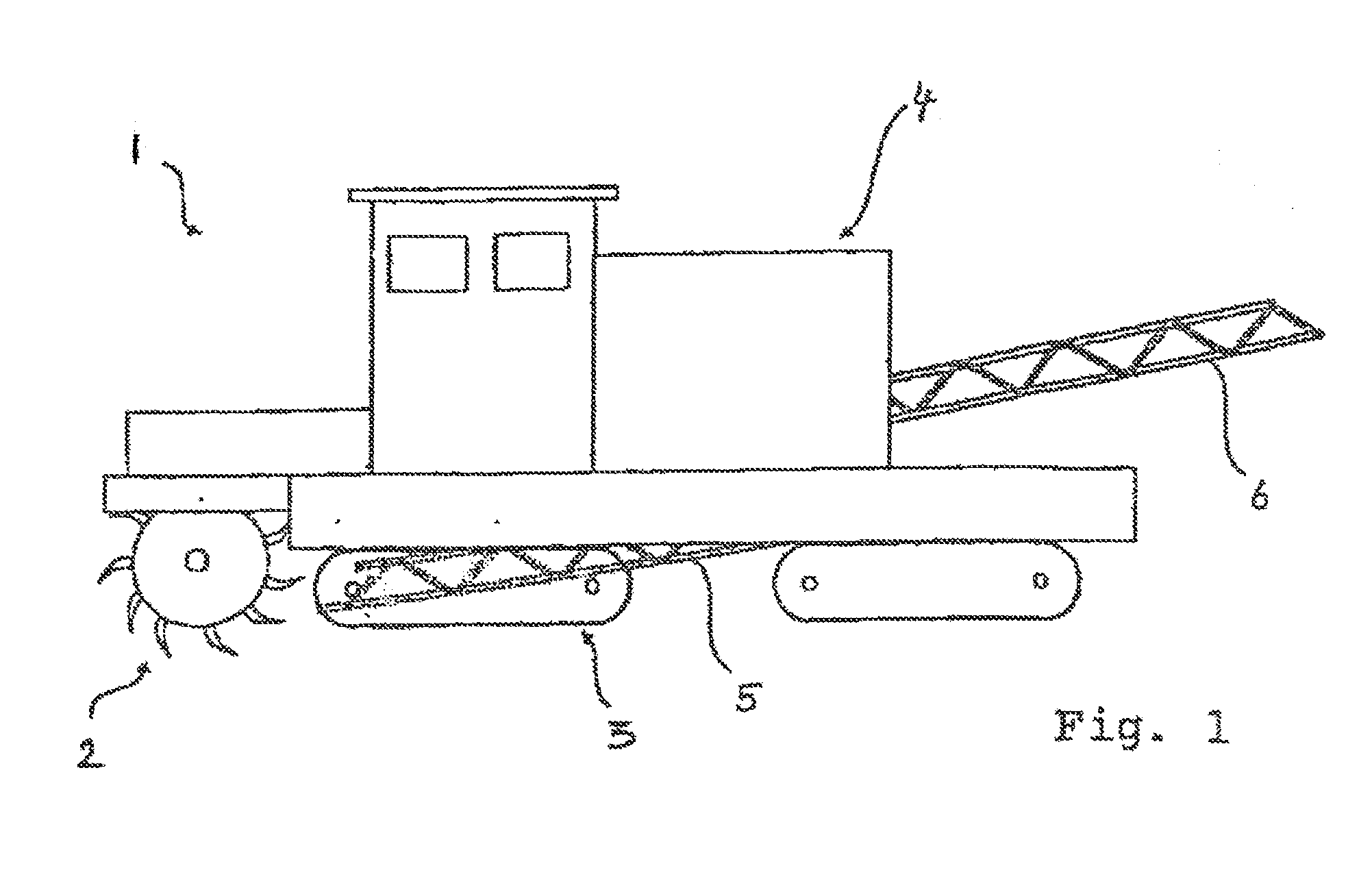
[0044]FIG. 1 shows a self-propelled surface milling cutter 1 such as a surface miner or asphalt milling cutter, whose main working assembly forms a milling drum 2 to be rotatably driven about a horizontal axis, on whose circumference cutting tools are mounted, in order to millingly comminute a ground layer or asphalt layer. The surface milling cutter 1 is moved continuously by means of the tracklaying gears 3, so that said milling drum 2 continuously experiences a feed movement. The machine body 4, which is drivably supported on the ground by said tracklaying gears 3 and carries said milling drum 2, furthermore comprises conveying means for removing the milled material. Coming from the milling drum, the milled material is charged onto a receiving conveyor 5, which transfers the material onto a loading conveyor 6, in order to load the comminuted material for example over onto a truck. Said receiving and loading conveyors 5 and 6 can, for example, be formed as belt systems.

[0045]Accor...


PUM


Abstract

The present disclosure relates to a self-propelled surface milling cutter, with a working assembly comprising a rotatingly drivable drum body, and at least one drum drive unit which is accommodated in the interior of the drum body and forms at least part of a rotatable bearing of the drum body on a drum supporting frame, wherein the at least one drum drive unit includes a stationary drive part attached to the drum supporting frame and a rotatable drive part connected with the drum body. The rotatable drive part of the drum drive unit is mounted on the drum body by a positive entrainment connection in a torque-transmitting, but longitudinally movable manner. The entrainment connection rotatorily entrains the drum body, in order to be able to transmit the rotary drive movements of the drive part to the drum body.

Description

CROSS REFERENCE TO RELATED APPLICATION[0001]This application claims priority to German Patent Application No. 10 2011 108 016.7, entitled “Self-Propelled Surface Milling Cutter,” filed Jul. 19, 2011, which is hereby incorporated in its entirety for all purposes.TECHNICAL FIELD[0002]The present disclosure relates to a self-propelled surface milling cutter, for example in the form of an asphalt milling cutter, a snow blower or a surface miner, with a working assembly comprising a rotatingly drivable drum body, and at least one drum drive unit which is accommodated in the interior of the drum body and forms at least part of a rotatable bearing of the drum body on a drum supporting frame, wherein the at least one drum drive unit includes a stationary drive part attached to the drum supporting frame and a rotatable drive part connected with the drum body.BACKGROUND AND SUMMARY[0003]Surface milling cutters, for example in the form of surface miners, are continuously operating open-pit min...

Claims


Application Information

Patent Timeline
IPC IPC(8): E01C23/088E21C25/08E01H5/09E01C23/12
CPCE01H5/098E21C31/00E01C23/088E21C27/24E21C47/00
Inventor HAUSLADEN, NORBERTSCHINDLER, VIKTOR
Owner LIEBHERR COMPONENTS BIBERACH GMBH
Why Eureka
Try Eureka