Pulsed operation of a discharge lamp

a discharge lamp and discharge lighting technology, applied in the field of discharge lamps, can solve the problems of exaggerated safety electrical designs, large dimensions of safe electrical designs to always obtain successful commutation, etc., and achieve the effects of increasing pulse height or width, reducing the loss of lamp efficiency, and increasing the luminous flux

Inactive Publication Date: 2013-02-14
KONINKLJIJKE PHILIPS NV
View PDF1 Cites 2 Cited by
  • Summary
  • Abstract
  • Description
  • Claims
  • Application Information

AI Technical Summary

Benefits of technology

[0022]According to a further embodiment of the invention, the lamp may be driven with pulses of increasing pulse height or width at least within a lifetime interval to obtain a higher luminous flux. In many lamps, lamp efficiency and thus the luminous flux obtained from a constant electrical power will decrease over the lamp lifetime, at least within intervals thereof. For example, for intervals of 500 h of lamp lifetime, a loss of lamp efficiency of e. g. some 2-10 lumens per Watt may be observed if the lamp is driven with constant electrical operation condition. The loss may vary between intervals in early lamp life or later lifetime. According to the preferred embodiment, this effect is countered by providing, at least within a lifetime interval of e. g. more than 300 h, preferably 900 h or more, pulses of increasing pulse height or width. These pulses may be the same pulses provided after commutation to ensure stable re-ignition of the lamp as discussed above. Alternatively or in addition thereto the increasing pulses may be provided at other times during each half period of the respective lifetime interval. Providing longer and/or higher current pulses increases the lamp efficiency. By providing increasing pulses, the loss of eff

Problems solved by technology

However, safe electrical designs dimensioned large enough to always obtain suc

Method used


Image

  • Pulsed operation of a discharge lamp
  • Pulsed operation of a discharge lamp
  • Pulsed operation of a discharge lamp

Examples


first embodiment

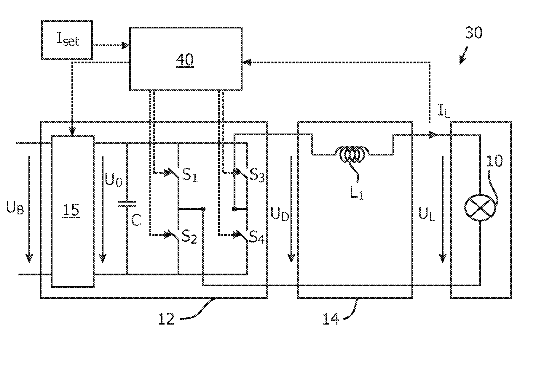
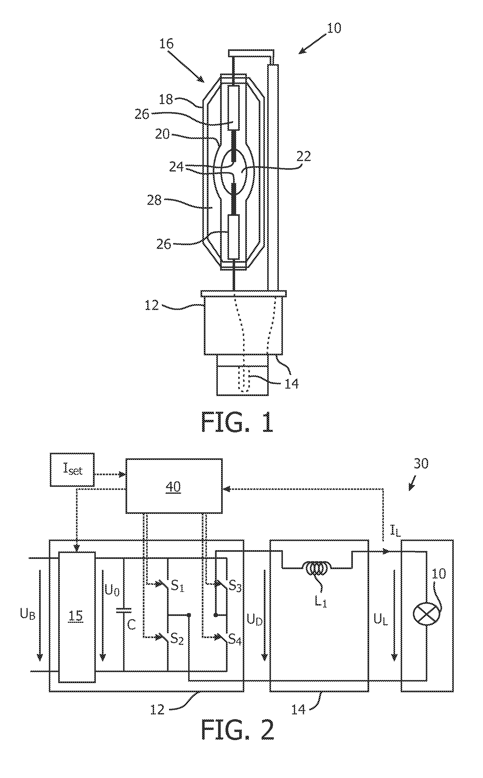
[0076]As shown in FIG. 4a for a first embodiment, the pulses 50 are applied directly after commutation. This prompts the closed-loop control of controller 40 in FIG. 2 to quickly raise the driver voltage UD after commutation.

second embodiment

[0077]In an alternative second embodiment of FIG. 4b, pulses are applied both before (pulses 52) and after (pulses 50) commutation.

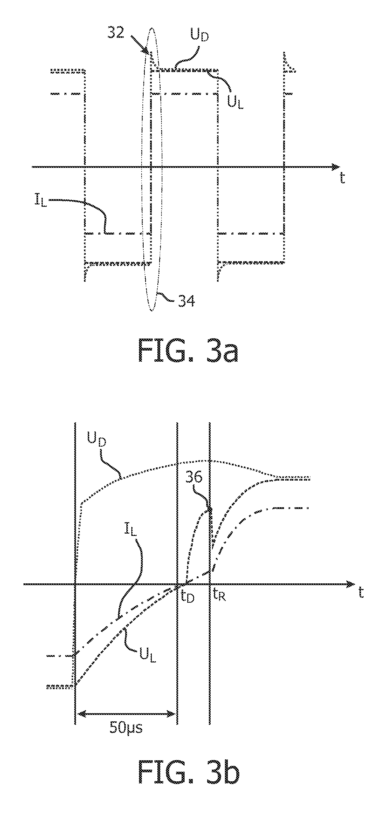
[0078]The present inventors have found that different values for the pulse width PW and the pulse height PH may be chosen to influence the dynamic voltage delivery capability of the driver 12. FIG. 7 shows a dependency of the maximum voltage UD obtainable after the defined delivery time tD of 50 μs after commutation in dependence on the pulse height PH. As shown, the dynamic capability of the driver 12 may thus be significantly influenced by the control applied from controller 40, without any further changes to the driver circuit 12. Thus, by choosing an appropriate pulse 50, a desired dynamic capability of the driver circuit 12 may be obtained.

[0079]However, it should be kept in mind that such pulses have drawbacks, such as increased losses and higher overall requirements for the elements of the circuit 30, such that the unnecessary application of pulse...


PUM


Abstract

A discharge lighting assembly and a method of operating a discharge lamp 10 are described. The discharge lamp 10 includes a discharge vessel 20 with two electrodes 24 for forming an arc discharge. A driver circuit 12 supplies electrical power to the lamp 10 as an alternating lamp current IL and/or an alternating lamp voltage UL with a commutation between half periods of positive and negative values. The driver circuit 12 is controlled to be able to deliver at a predetermined delivery time tD of 10-100 μs after commutation a voltage level Up which varies in dependence on the lifetime L of the lamp 10.

Description

FIELD OF THE INVENTION[0001]The present invention relates to the field of discharge lamps and more specifically to a discharge lighting assembly and a method of operating a discharge lamp.BACKGROUND OF THE INVENTION[0002]In a discharge lamp, light is generated from an arc discharge ignited between two electrodes in a discharge vessel. Discharge lamps, specifically high pressure gas discharge lamps are used in numerous lighting applications today, specifically for automotive front lighting.[0003]For high pressure gas (Xenon) discharge lamps, it is known to operate the lamps in a discharge lighting assembly which includes, besides the discharge lamp itself, an ignition circuit for supplying a high ignition voltage to start the lamp, a driver circuit for supplying electrical power to the lamp and a controller to control operation of the driver circuit.[0004]WO 95 / 35645 A1 describes a method and circuit arrangement for operating a high pressure discharge lamp. To avoid flicker due to an...

Claims


Application Information

Patent Timeline
IPC IPC(8): H05B41/39
CPCH05B41/2928Y02B20/202H05B41/3928Y02B20/00
Inventor HAACKE, MICHAELDABRINGHAUSEN, LARSDE KONING, EDWIN THEODORUS MARIABALM, JEROEN
Owner KONINKLJIJKE PHILIPS NV
Why Eureka
Try Eureka